Body Electrical System
Junction Box (Passenger Compartment)
In this manual: Body Electrical System
20steps
~120min
4/5difficulty
Done 0 of 20
Components and Component Location
Component Location
I/P Junction Box

Circuit (I/P Junction Box)

Description and Operation
Description
Communication Network Diagram
| Abbreviation | Description |
| ABS | Anti-Lock Braking System (ABS) |
| ACU | Airbag Control Unit |
| AEB | Autonomous Emergency Braking |
| B-CAN | Body Controller Network |
| BCM | Body Control Module |
| C-CAN | Chassis Controller Area Network |
| CLU | Cluster Module |
| DATC | Dual Automatic Temperature Control |
| Emergency Call | Engine Control System |
| ESC | Electronic Control Suspension |
| EVP | Electric Vacuum Pump (EVP) |
| I-BOX | Telematics System |
| LPI | Liquid Oil Injection |
| H_U | Head Unit (Audio/AVN) |
| M-CAN | Multimedia Controller Network |
| MDPS | Motor Driven Power Steering |
| PGS | Park Assist System |
| UUZR | Seat Belt Reminder and Lighting Module |
| SMK | Smart Key Unit |
| TCU | Transmission Control Unit |
| TMU | Telematics System |
| SCP | Tire Pressure Monitoring System |
Repair Procedures
Fuse Inspection
- Make sure the fuse holders are secured and that the fuses are firmly retained by the holders.
- Make sure that each fuse circuit has the correct fuse rating.
- Inspect the fuses for damage.
Diagnosis Using KDS/GDS
- The interior junction block can be diagnosed using KDS/GDS. The interior junction block communicates with KDS/GDS, which then displays the inputs and outputs together with the codes.
- To diagnose the interior junction block function, select the vehicle model "Interior".
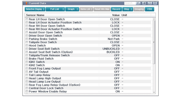
- Refer to the current input/output values of the interior junction block in "Current Data". It provides information on the input/output conditions of the interior junction block.
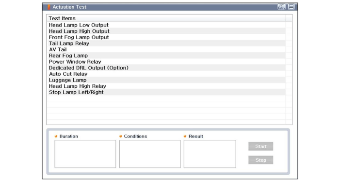
- To perform a functional check of the interior junction block outputs, select "Actuation Test".
Removal
- Disconnect the negative (-) battery terminal.
- Remove the emergency pad lower panel. (Refer to Body - "Emergency Pad Lower Panel")
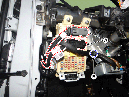
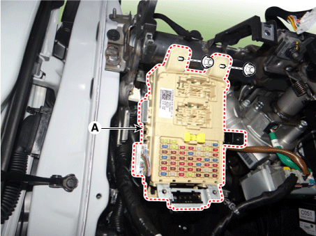
- Disconnect the connectors (A) on the fuse side of the interior junction block.
- Remove the wiring harness clip of the interior junction block (B).
- Remove the side connectors of the interior junction block (A).
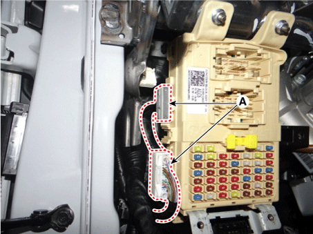
- Remove the interior junction block (A) after loosening the mounting nuts.
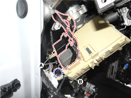
- Disconnect the connectors (A) from the rear of the interior junction block.
- Remove the wiring harness clip of the interior junction block (B).
Installation
- Install the interior junction block.
- Connect the connectors of the interior junction block.
- Install the emergency pad lower panel.
- Connect the negative (-) battery terminal.
- Make sure all systems operate properly.
Test yourself
A quick Kia Picanto JA quiz: every answer comes with an explanation and a link to the manual page.
Was this page helpful?