Engine Mechanical K9K

Injection tube and fuel injector

In this manual: Engine Mechanical K9K
Foreword — 1General information — 45Engine Mechanical MR16DDT — 61Engine Mechanical HR16DE — 52Engine Mechanical K9K — 46Engine Lubrication System MR16DDT — 18Engine Lubrication System HR16DE — 14Engine Lubrication System K9K — 11Engine Cooling System MR16DDT — 28Engine Cooling System HR16DE — 29Engine Cooling System K9K — 24Engine Control System MR16DDT — 163Engine Control System HR16DE — 115Engine Control System K9K — 129Fuel System MR16DDT — 13Fuel system HR16DE — 11Fuel system K9K — 12Exhaust system MR16DDT — 7Exhaust system HR16DE — 10Exhaust system K9K — 7Starting system — 24Accelerator control system — 6Clutch — 25Driveline transfer: TY21B — 77Driveline rear propeller Shaft: 3Fφ16-ETJ75 — 12Driveline rear final drive: RTVS — 31Transaxle & transmission 5MT: RS5F92R — 31Transaxle & transmission 6MT: RS6F94R — 30Transaxle & transmission CVT: RE0F10B — 93Transaxle & transmissioN CVT: RE0F11A — 103Front Axle MR16DDT — 18Front Axle HR16DE — 17Front Axle K9K — 17Rear Axle 2WD — 6Rear Axle 4WD — 13Front Suspension — 21Rear Suspension 2WD — 13Rear Suspension 4WD — 17Road Wheels & Tires — 6Brake System LHD — 24Brake System RHD — 24Parking Brake System — 8Brake Control System without ESP — 44Brake Control System with ESP — 63Steering System — 14Steering Control System — 27Seat Belt — 8SRS Airbag — 24SRS Airbag Control System — 93Ventilation System — 11Heater & Air Conditioning System HR16DE — 28Heater & Air Conditioning System MR16DDT — 28Heater & Air Conditioning Control System Type 1 — 49Heater & Air Conditioning Control System Type 2 — 51Heater & Air Conditioning Control System Type 3 — 32Heater & Air Conditioning Control System Type 4 — 40Heater & Air Conditioning Control System Type 5 — 21Interior — 16Instrument Panel — 10Seat — 18Door & Lock Type 1 — 83Door & Lock type 2 — 80Door & Lock type 3 — 65Door & Lock type 4 — 60Security Control System with intelligent key system — 82Security Control System without intelligent key system — 41Glass & Window System — 15Power Window Control System — 28Body Repair — 13Exterior — 20Mirrors — 26Exterior Lighting System Halogen type — 51Interior Lighting System — 24Wiper & Washer — 45Defogger — 31Horn — 4Power Outlet — 4Body Control System With intelligent key system — 21Body Control System Without intelligent key system — 23LAN system can fundamental — 6LAN system can — 31LAN System can system (type 1) — 1LAN System can system (type 2) — 1LAN System can system (type 3) — 1LAN System can system (type 4) — 1LAN System can system (type 5) — 1LAN System can system (type 6) — 1LAN System can system (type 7) — 2LAN System can system (type 8) — 1LAN System can system (type 9) — 1LAN System can system (type 10) — 1LAN System can system (type 11) — 1Power Control System IPDM E/R (with I-key) — 14Power Control System IPDM E/R (without I-key) — 14Power Control System Power distribution system — 25Charging System — 22Power Supply, Ground & Circuit Elements — 20Meter, Warning Lamp & Indicator — 33Warning Chime System — 22Audio, Visual & Navigation System Audio without navigation — 30Audio, Visual & Navigation System Audio with navigation — 33Audio, Visual & Navigation System NISSAN dynamic control system — 22Cruise Control System — 1Drive Mode System — 10Maintenance — 14
~3min read
010203040503022N·mlb·ft
Tightening torque found on this page

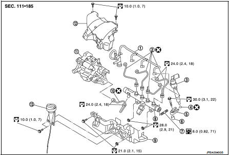
Exploded View

1. Spill hose

1. Spill hose
2. Injection tube
3. Fuel injector
4. Heat protection washer 5. Fuel injector bracket 6. Fuel injector bracket spacer 7. Fuel rail stud bolt
8. Fuel rail
9. High pressure protection cover (lower) 10. Injection tube
11. High pressure supply pump 12. High pressure protection cover (upper) 13. Oil level gauge guide

: N·m (kg-m, in-lb): N·m (kg-m, ft-lb)
: Always replace after every: N·m (kg-m, in-lb)
disassembly.: Always replace after every
disassembly.

Removal and Installation

REMOVAL

CAUTION:
• Be sure to read “Precautions for Diesel Equipment”. Refer to EM-263, "Precaution for Diesel Equipment". • Wait until the fuel temperature drops before carrying out any work. • Order the special high pressure injection circuit plug kit. • It is forbidden to open an injector. If you open an injector by mistake, you will have to change it. This is because of the manufacturing and installation tolerances and because there is a risk of contaminating the inside of the injector.

• The rod filter of the injector must not be removed.

NOTE: It is possible to replace a single injection tube. 1. Disconnect the battery cable from negative terminal. 2. Remove air inlet tube assembly and air inlet tube. Refer to EM-281, "Exploded View". 3. Remove oil level gauge guide and plug the hole. 4. Remove injection tube protection cover. 5. Remove the neck located on the fuel rail, NOTE

:
Undo the nut on the pump side or the injector side, then the nut located on the rail side. Undo the nuts for each pipe in turn. Move the nut along the pipe keeping the olive in contact with the taper.

6. Remove all the injection tubes. 7. Plug all the holes in the injection circuit. 8. Remove fuel rail. 9. Disconnect fuel return pipe.

10. Manually remove the injector diesel return hose.

CAUTION:
Do not force on the diesel injector return hose
11. Plug all the holes of the injection circuit. 12. Disconnect the injector harness connector. 13. Unscrew the injector bracket. 14. Remove the injector.

15. Pull off the flame shield washer.

INSTALLATION

CAUTION:
All the injection tubes removed must be systematically replaced.
1. Clean the injector sockets and the injector bodies, as well as their brackets using a lint-free cloth (use the wipes recommended for this purpose, dipped in clean solvent. 2. Dry off using a different new wipe. 3. Replace the flame shield washer with a new one. 4. Position the injector.

5. Tighten its mounting bracket.

6. Install injection tubes with new one.: 30 N·m


6. Install injection tubes with new one. 7. Finger tightens the nuts.

8. Before fitting the new injection tubes, lightly lubricate the nut threads with the oil from the sachet provided in the new parts kit.

NOTE

:
Fit the pump/rail pipe before the rail/injector tubes.

9. Fit the pump-rail injection tube as follow: • Remove the protective plugs from the high pressure pump outlet, the high pressure rail inlet and the pipe. • Insert the injection tube olive into the taper of the high pressure pump outlet,
• Insert the injection tube olive into the taper of the high pressure rail inlet.

• Finger tighten the nuts of the injection tube starting with the one located on the rail side.

10. Install the rail-injector injection tube.

11. Tighten the injection tube nut.

12. Connect fuel return pipe.: 24 N·m


12. Connect fuel return pipe.

13. Install in the reverse order to removal for the other refitting operations.