Valve Timing Control
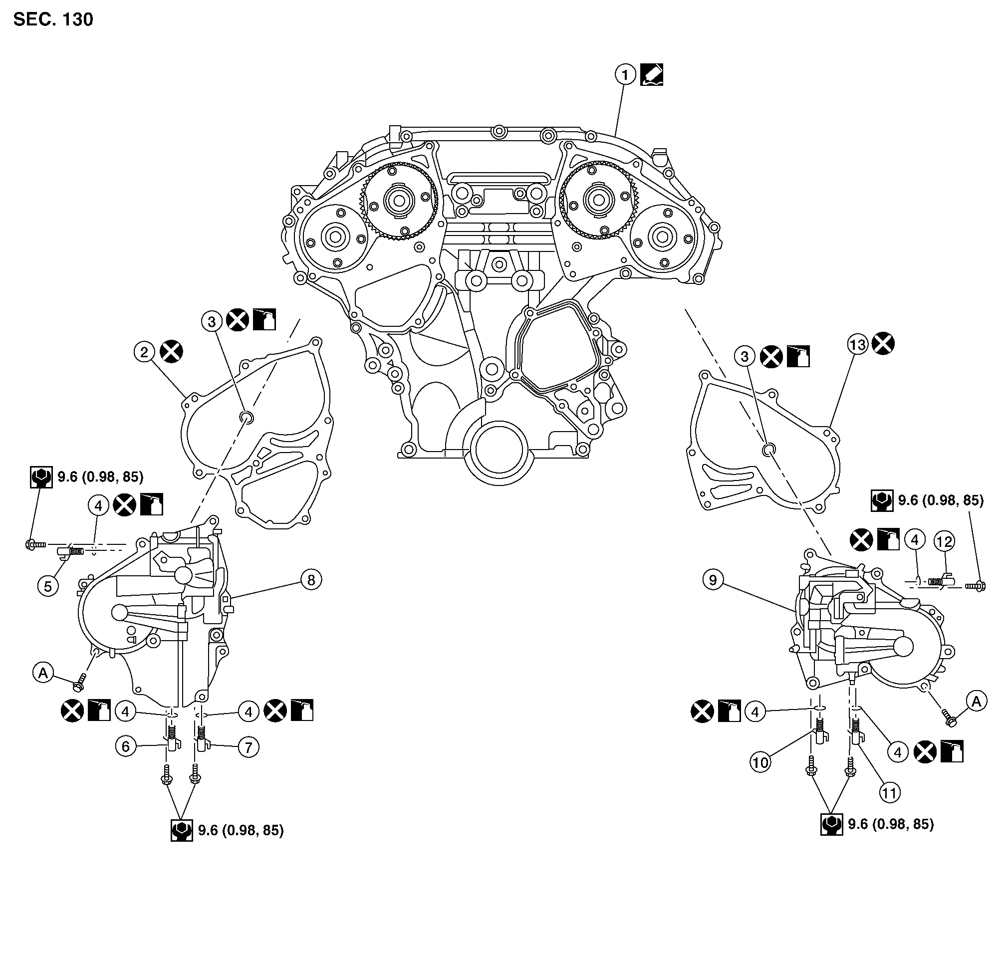
| 1. | Front timing chain case | 2. | Valve timing control cover gasket (bank 1) | 3. | O-ring |
| 4. | O-ring | 5. | Intake valve timing intermediate lock control solenoid valve (bank 1) | 6. | Exhaust valve timing control solenoid valve (bank 1) |
| 7. | Intake valve timing control solenoid valve (bank 1) | 8. | Valve timing control cover (bank 1) | 9. | Valve timing control cover (bank 2) |
| 10. | Intake valve timing control solenoid (bank 2) | 11. | Exhaust valve timing control solenoid (bank 2) | 12. | Intake valve timing intermediate lock control solenoid valve (bank 2) |
| 13. | Valve timing control cover gasket (bank 2) | A. | Refer to Removal and Installation (bank 1) or Removal and Installation (bank 2). |
REMOVAL
Disconnect battery negative terminal. Refer to Removal and Installation.
Remove core support cover. Refer to Exploded View.
Remove front air duct. Refer to Exploded View.
Remove cowl top and cowl top extension. Refer to Exploded View.
Remove reservoir tank. Refer to Exploded View.
Remove power steering oil pump. Refer to Removal and Installation.
Support engine (1) and transaxle (2) using suitable jack (A).
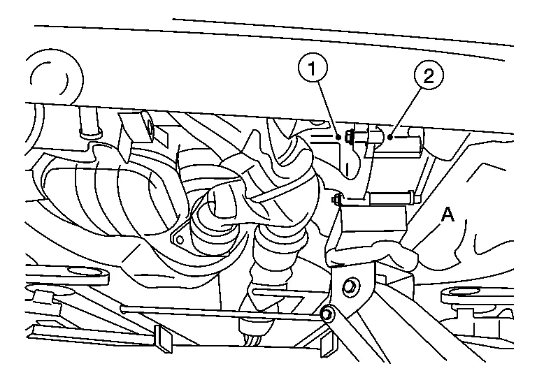
Remove upper torque rod, engine mounting insulator (RH), and engine mounting bracket (RH). Refer to Exploded View (FWD) or Exploded View (AWD).
Disconnect the harness connector from intake valve timing intermediate lock control solenoid valve (bank 1).
Disconnect the harness connector from exhaust valve timing control solenoid valve (bank 1).
Disconnect the harness connector from intake valve timing control solenoid valve (bank 1).
Remove intake valve timing intermediate lock control solenoid valve (bank 1), exhaust valve timing control solenoid valve (bank 1), and intake valve timing control solenoid valve (bank 1) from valve timing control cover (bank 1).
Remove the valve timing control cover (bank 1) and gasket.
INSTALLATION
Install valve timing control cover (bank 1). Refer to Exploded View.
Installation of remaining components is in the reverse order of removal.
Do not reuse O-rings.
Lubricate O-rings with clean engine oil prior to installation.
REMOVAL
Remove core support cover. Refer to Exploded View.
Remove front air duct. Refer to Removal and Installation.
Remove reservoir tank. Refer to Exploded View.
Remove power steering oil pump. Refer to Removal and Installation.
Disconnect the harness connector from intake valve timing intermediate lock control solenoid valve (bank 2).
Disconnect the harness connector from exhaust valve timing control solenoid valve (bank 2).
Disconnect the harness connector from intake valve timing control solenoid valve (bank 2).
Remove intake valve timing intermediate lock control solenoid valve (bank 2), exhaust valve timing control solenoid valve (bank 2), and intake valve timing control solenoid valve (bank 2) from valve timing control cover (bank 2).
Remove valve timing control cover (bank 2) and gasket.
INSTALLATION
Install valve timing control cover (bank 2). Refer to Exploded View.
Installation of remaining components is in the reverse order of removal.
Do not reuse O-rings.
Lubricate O-rings with clean engine oil prior to installation.