Fuel Injector and Fuel Tube
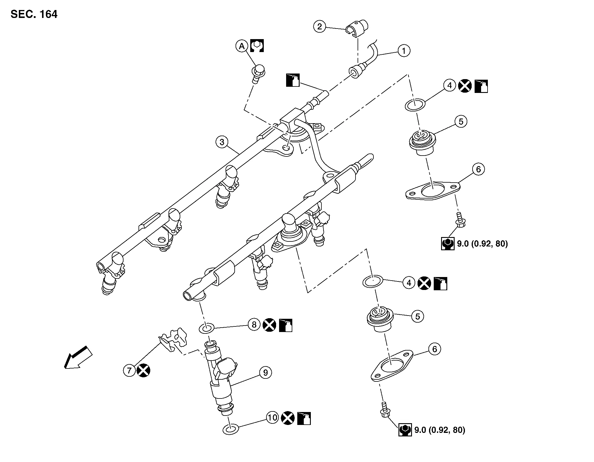
| 1. | Fuel feed hose | 2. | Quick connector cap | 3. | Fuel tube |
| 4. | O-ring | 5. | Fuel damper | 6. | Fuel damper cap |
| 7. | Clip | 8. | O-ring (black) | 9. | Fuel injector |
| 10. | O-ring (green) | A. | Refer to Removal and Installation. |  |
Engine front |
REMOVAL
Remove engine room cover. Refer to Removal and Installation.
Release the fuel pressure. Refer to Work Procedure.
Disconnect the battery negative terminal. Refer to Removal and Installation.
Remove intake manifold collector. Refer to Removal and Installation.
When separating fuel feed hose and fuel tube connection, disconnect quick connector using Tool as follows:
| Tool number | : 16441 6N210 (J-45488) |
With the sleeve side of Tool facing toward the quick connector, install the Tool onto fuel tube.
Insert the Tool (A) into quick connector (2) until sleeve (B) contacts and goes no further. Hold Tool in that position.

(C) : Insert and retain Draw and pull out quick connector straight from fuel tube (1).
Disconnect harness connector from fuel injector.
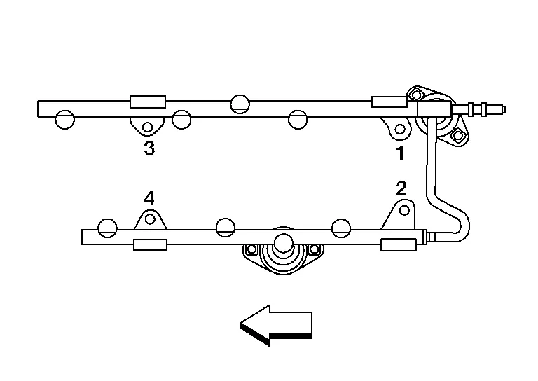
Loosen bolts in reverse order as shown, and remove fuel tube and fuel injector assembly.
|
: Engine front |
Remove fuel injector from fuel tube as follows:Open and remove clip (1).
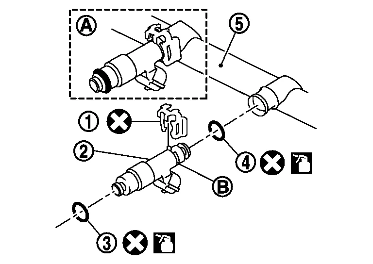
| (3) | : O-ring (green) |
| (4) | : O-ring (black) |
| (A) | : Installed condition |
| (B) | : Clip mounting groove |
Remove fuel damper from fuel tube.
INSTALLATION
Install fuel damper as follows:Install new O-ring (2) to fuel tube (1) as shown. When handling new O-ring, be careful of the following caution:
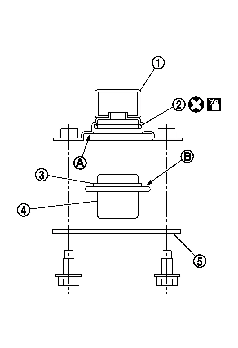
After tightening bolts, check that there is no gap between fuel damper cap (5) and fuel tube.
Install new O-rings to fuel injector paying attention to the following.
Install fuel injector to fuel tube as follows:Insert clip (3) into clip groove (F) on fuel injector (5).
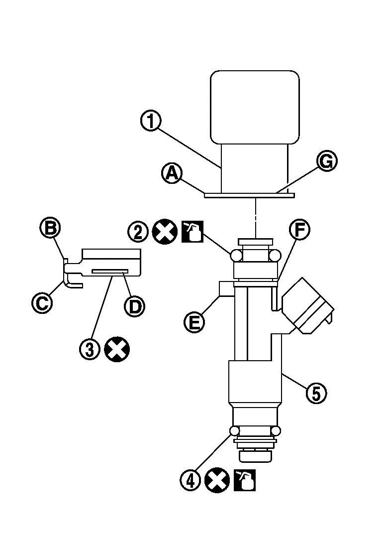
- : O-ring (black)
- : O-ring (green)
Insert clip so that protrusion (E) of fuel injector matches cutout (C) of clip.
Insert it while matching it to the axial center.
Insert fuel injector so that protrusion (A) of fuel tube matches cutout (B) of clip.
Check that fuel tube flange (G) is securely fixed in flange groove (D) on clip.
| Reference value | : 147 N (15.0 kg, 33.0 lb) |
Check that protrusions of fuel injectors and fuel tubes are aligned with cutouts of clips after installation.
Install fuel tube and fuel injector assembly to intake manifold.
Tighten bolts in two steps in numerical order as shown.
: Engine front 1st step : 10,1 N·m 2nd step : 22 N·m
Connect fuel injector harness.
Install intake manifold collector. Refer to Removal and Installation.
Connect quick connector between fuel feed hose and fuel tube connection with the following procedure:Check no foreign substances are on the fuel tube or quick connector and that they are not damaged. Apply a light coating of new engine oil around fuel tube from tip end to spool end. Align center to insert quick connector straightly into fuel tube.
Insert quick connector (1) to fuel tube until top spool (2) is completely inside quick connector, and 2nd level spool (3) exposes right below quick connector.

(B) : Installed condition : Upright insertion

| (1) | : Fuel feed hose |
| (2) | : Fuel tube |
| (B) | : Upper view |
Install quick connector cap with arrow (A) on surface facing in direction of quick connector (fuel feed hose side).
Installation of the remaining components is in the reverse order of removal.
INSPECTION AFTER INSTALLATION
Check For Fuel Leaks
Turn ignition switch ON with the engine stopped. With fuel pressure applied to fuel piping, check for fuel leaks at connection points. Repair as necessary.
Start the engine. With engine speed increased, check again for fuel leaks at connection points. Repair as necessary.
Perform procedures for “Throttle Valve Closed Position Learning” after finishing repairs. Refer to Description.
If electric throttle control actuator is replaced, perform procedures for “Idle Air Volume Learning” after finishing repairs. Refer to Description.