Injector spacer plate
K4J
Tightening torques |
|
| injector spacer plate bolts 11 and 12 | 2.5 daN.m |
| injector spacer plate bolts 13 to 20 | 2.1 daN.m |
| upper timing cover bolt | 4.4 daN.m |
| pendulum mount bracket bolt | 4.4 daN.m |

REMOVAL
- Disconnect the battery.
- Remove the intake manifold (Chapter Air-Fuel Mixture, Intake Manifold, page 12A-26).
Beware of fuel spray when disconnecting the fuel supply fitting from the fuel rail.
WARNINGProtect the alternator from fuel flowing out of the rail and the supply pipe.
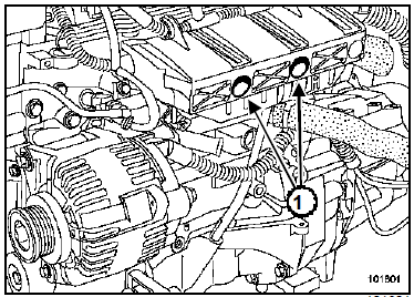
- Remove the two fuel rail cover retaining nuts (1).
- Release the wiring harness.
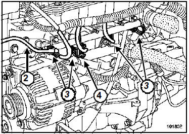
- Disconnect:
- the fuel inlet fitting (2),
- the injectors (3),
- the knock sensor (4).
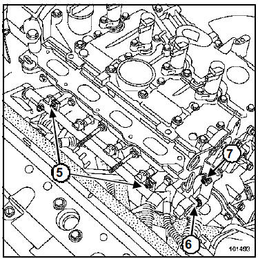
- Remove the two fuel rail retaining bolts (5).
- Carefully pull the fuel rail towards you to remove it.
- Remove:
- the wiring harness retaining nut (6),
- the oil dipstick tube (7).
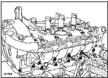
- Remove the injector spacer plate retaining bolts.
INSTALLATION
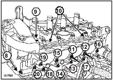
- Always replace the injector spacer plate gasket.
- Fit all retaining bolts.
- Press the injector spacer plate against the upper timing cover and start bolt (8) by hand.
- Press the injector spacer plate against the engine pendulum mount bracket and tighten bolt (9) by hand.
- Position the injector spacer plate resting on the rocker cover spacers (10).
- Tighten in the following order and to the following torques:
- injector spacer plate retaining bolts 11 and 12 (2.5 daN.m),
- injector spacer plate retaining bolts 13 to 20 (2.1 daN.m).
- Tighten to the following torques:
- upper timing cover bolt (4.4 daN.m),
- pendulum mount bracket bolt (4.4 daN.m).
- Refit in the reverse order of removal.
Connect the battery; carry out the necessary re-learns (see Electrical Equipment chapter).
K4M
Tightening torques |
|
| injector spacer plate bolts 5 and 6 | 2.5 daN.m |
| injector spacer plate bolts 7 to 14 | 2.1 daN.m |
| pendulum mount bracket bolt | 4.4 daN.m |
| upper timing cover bolt | 4.4 daN.m |

REMOVAL
- Disconnect the battery.
- Remove the intake manifold (Chapter Air-Fuel Mixture, Intake Manifold, page 12A-26).
Beware of fuel spray when disconnecting the fuel supply fitting from the fuel rail.
WARNINGProtect the alternator from fuel flowing out of the rail and the supply pipe.
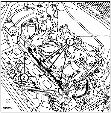
- Disconnect the injectors (1).
- Release the wiring harness.
- Remove:
- the two fuel rail retaining bolts (2),
- the fuel rail by carefully pulling it towards you.
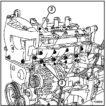
- Remove the injector spacer plate retaining bolts (3).
INSTALLATION
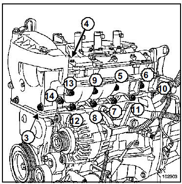
- Always replace the injector spacer plate gasket.
- Fit all retaining bolts.
- Press the injector spacer plate against the upper timing cover and start bolt (3) by hand.
- Press the injector spacer plate against the engine pendulum mount bracket and tighten bolt (4) by hand.
- Tighten in the following order and to the following torques:
- injector spacer plate bolts 5 and 6 (2.5 daN.m),
- injector spacer plate bolts 7 to 14 (2.1 daN.m),
- Tighten to the following torques:
- pendulum mount bracket bolt (4.4 daN.m),
- upper timing cover bolt (4.4 daN.m).
- Refit in the reverse order of removal.
Connect the battery; carry out the necessary re-learns (see Electrical Equipment chapter).
F4R
Tightening torques |
|
| injector spacer plate bolts 7 and 8 | 2.5 daN.m |
| injector spacer plate bolts 9 to 16 | 2.1 daN.m |
| pendulum mount bracket bolt 6 | 4.4 daN.m |
| upper timing cover bolt 5 | 4.4 daN.m |

REMOVAL
- Disconnect the battery.
- Remove the intake manifold (Chapter Air-Fuel Mixture, Intake Manifold, page 12A-26).
Beware of fuel spray when disconnecting the fuel supply fitting from the fuel rail.
WARNINGProtect the alternator from fuel flowing out of the rail and the supply pipe.
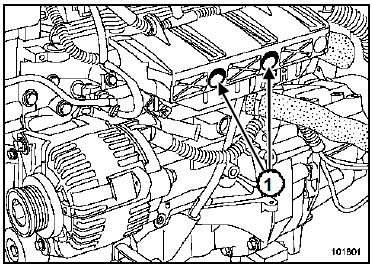
- Remove the two fuel rail cover retaining nuts (1).
- Release the wiring harness.
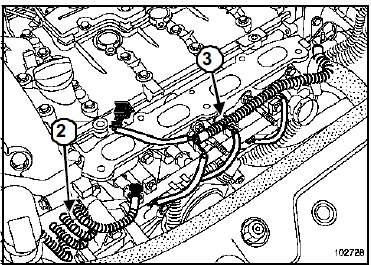
- Disconnect:
- the fuel inlet fitting (2),
- the injector harness (3).
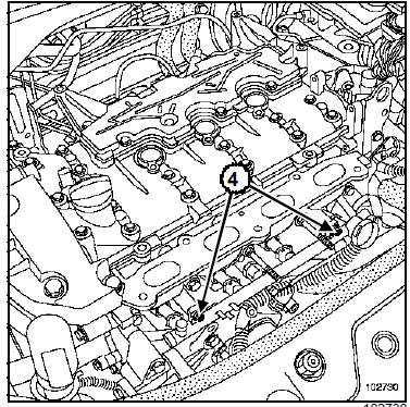
- Remove:
- the two fuel rail retaining bolts (4),
- the fuel rail by carefully pulling it towards you.
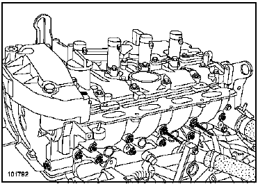
- Remove the injector spacer plate retaining bolts.
INSTALLATION
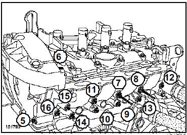
- Always replace the injector spacer plate gasket.
- Fit all retaining bolts.
- Press the injector spacer plate against the upper timing cover and start bolt (5) by hand.
- Press the injector spacer plate against the pendulum mount bracket and start bolt (6) by hand.
- Tighten in the following order and to the following torques:
- injector spacer plate bolts 7 and 8 (2.5 daN.m),
- injector spacer plate bolts 9 to 16 (2.1 daN.m),
- Tighten to the following torques:
- pendulum mount bracket bolt 6 (4.4 daN.m),
- upper timing cover bolt 5 (4.4 daN.m).
- Refit in the reverse order of removal.
Connect the battery; carry out the necessary re-learns (see Electrical Equipment chapter).
Test yourself
A quick Renault Megane quiz: every answer comes with an explanation and a link to the manual page.