Reassembly
1. INSTALL DUST SEAL
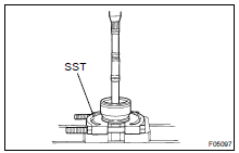
Using SST and a press, install a new dust seal to the outboard joint shaft.
SST 09950-00020
NOTICE: Be careful not to damage the dust seal.
2. INSTALL DUST COVER

Using SST a steel plate and press, install a new dust cover.
SST 09316-2001 1
NOTICE: Be careful not to damage the dust cover.
3. INSTALL OUTBOARD JOINT BOOT AND CLAMPS
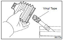
(a) Place 2 new boot clamps to boot.
HINT: Before installing the boot, wrap vinyl tape around the spline of the shaft to prevent damaging the boot.
(b) Temporarily install a new boot to the outboard joint shaft.
(c) Position the inside clamp onto the boot.

(d) Using SST, pinch the inside clamp.
SST 09521-24010
NOTICE: Do not overtighten SST.
(e) Pack the outboard joint and boot with grease in the boot kit.
Grease capacity: 368 - 378 g (13.0 - 13.3 oz.)
(f) Position the outside clamp onto the boot.
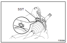
(g) Using SST, pinch the outside clamp.
SST 09521-24010
NOTICE: Do not overtighten SST.
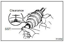
(h) Using SST, adjust the clearance of the clamps.
SST 09240-00020
Clearance: 0.8 mm (0.031 in.)
4. TEMPORARILY INSTALL INBOARD JOINT BOOT AND CLAMPS
Temporarily install 2 new boot clamps and boot to the outboard joint shaft.
5. ASSEMBLE INBOARD JOINT
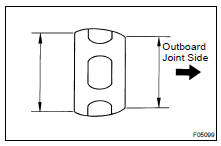
(a) Install the cage to the outboard joint shaft.
NOTICE: Insert the cage with its smaller inner diameter side facing to the outboard joint.
(b) Align matchmarks placed before removal.
(c) Install the inner race.
(d) Using a snap ring expander, install a new snap ring.
(e) Align matchmarks placed before removal, and install the cage to the inner race.
(f) Install the 6 balls.
HINT: Apply grease onto the balls to keep them from falling.
(g) Pack the inboard joint tulip and boot with grease in the boot kit.
Grease capacity: 293 - 303 g (10.3 - 10.7 oz.)
(h) Align matchmarks placed before removal, and install the inboard joint tulip to the outboard joint shaft.
(i) Install a new snap ring.
(j) Temporarily install the boot to the inboard joint tulip.
(k) Make sure that the boot is on the shaft groove.
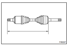
(l) Make sure that the 2 boots are not stretched or contracted when the drive shaft is at standard length.
Drive shaft standard length: 573.9 +- 5.0 mm (22.594 +- 0.197 in.)
(m) Using a screwdriver, bend the clamps and lock them.
6. CHECK DRIVE SHAFT (SA-29 )
Test yourself
A quick Toyota Land Cruiser quiz: every answer comes with an explanation and a link to the manual page.