LVL Terminal Circuit
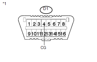
- By connecting terminals LVL and CG of the DLC3, the headlight leveling ECU assembly initializes the height control sensor signal.

PROCEDURE
CHECK HARNESS AND CONNECTOR (DLC3 - HEADLIGHT LEVELING ECU ASSEMBLY)
(a) Disconnect the A40 headlight leveling ECU assembly connector. |
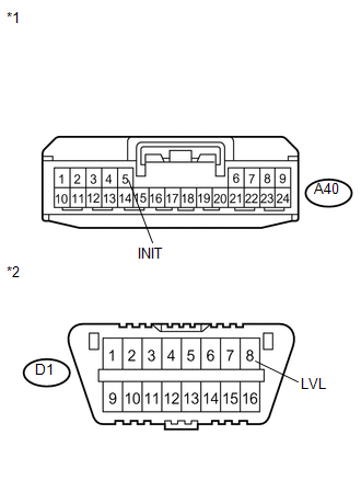 |
(b) Measure the resistance according to the value(s) in the table below.
Standard Resistance:
Tester Connection | Condition | Specified Condition |
|---|---|---|
A40-5 (INIT) - D1-8 (LVL) |
Always |
Below 1 Ω |
A40-5 (INIT) - Body ground |
Always |
10 kΩ or higher |
*1 |
Front view of wire harness connector (to Headlight Leveling ECU Assembly) |
*2 |
DLC3 |
| NG |  | REPAIR OR REPLACE HARNESS OR CONNECTOR |
|

CHECK HARNESS AND CONNECTOR (DLC3 - BODY GROUND)
(a) Measure the resistance according to the value(s) in the table below. Standard Resistance:
|
 |
| OK | | PROCEED TO NEXT SUSPECTED AREA SHOWN IN PROBLEM SYMPTOMS TABLE |
| NG | | REPAIR OR REPLACE HARNESS OR CONNECTOR |
Test yourself
A quick Toyota Venza quiz: every answer comes with an explanation and a link to the manual page.