Theft Deterrent System Communication Line High Fixation (B279A)
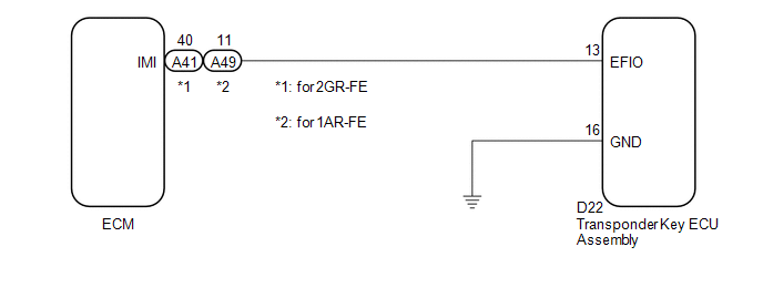
If the communication line (EFIO-IMI) to the transponder key ECU assembly is stuck high output (e.g. shorted to +B), the ECM stores this DTC.
DTC No. | DTC Detection Condition | Trouble Area |
|---|---|---|
B279A |
Communication line (EFIO-IMI) between the ECM and transponder key ECU assembly is stuck high output. |
|
CAUTION / NOTICE / HINT
NOTICE:
- If the transponder key ECU assembly is replaced, register the key and ECU communication ID (See page
 ).
- If the ECM is replaced, register the ECU communication ID (See page ).
CHECK DTC OUTPUT
(a) Recheck for DTCs (See page ).
HINT:
If any DTCs other than DTC B279A are output, troubleshoot those DTCs first.
Result | Proceed to |
|---|---|
DTC B279A is output |
A |
DTC B279A and other DTCs are output |
B |
| B |  | GO TO DTC CHART |
|

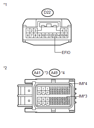
CHECK HARNESS AND CONNECTOR (TRANSPONDER KEY ECU - ECM)
(a) Disconnect the transponder key ECU assembly connector.
(b) Disconnect the ECM connector. |
 |
(c) Measure the resistance and voltage according to the value(s) in the table below.
Standard Resistance:
for 2GR-FETester Connection | Condition | Specified Condition |
|---|---|---|
D22-13 (EFIO) - A41-40 (IMI) |
Always |
Below 1 Ω |
D22-13 (EFIO) - Body ground |
Always |
10 kΩ or higher |
A41-40 (IMI) - Body ground |
Always |
10 kΩ or higher |
Tester Connection | Condition | Specified Condition |
|---|---|---|
D22-13 (EFIO) - A49-11 (IMI) |
Always |
Below 1 Ω |
D22-13 (EFIO) - Body ground |
Always |
10 kΩ or higher |
A49-11 (IMI) - Body ground |
Always |
10 kΩ or higher |
Standard Voltage:
Tester Connection | Condition | Specified Condition |
|---|---|---|
D22-13 (EFIO) - Body ground |
Always |
Below 1 V |
*1 |
Front view of wire harness connector (to Transponder Key ECU Assembly) |
*2 |
Front view of wire harness connector (to ECM) |
*3 |
for 2GR-FE |
*4 |
for 1AR-FE |
| NG | | REPAIR OR REPLACE HARNESS OR CONNECTOR |
|
CHECK TRANSPONDER KEY ECU ASSEMBLY (OUTPUT)
(a) Reconnect the transponder key ECU assembly connector.
(b) Reconnect the ECM connector.
(c) Using an oscilloscope, check the waveform. Waveform 1 (Reference):
Result:
|
 |
| B | | REPLACE ECM |
| C | | REPLACE ECM |
|
REPLACE TRANSPONDER KEY ECU ASSEMBLY
(a) Replace the transponder key ECU assembly (See page ).
|
REGISTER KEY
(a) Register the key (See page ).
|
REGISTER ECU COMMUNICATION ID
(a) Register the ECU communication ID (See page ).
|
CHECK DTC OUTPUT
(a) Clear the DTCs (See page ).
(b) Recheck for DTCs (See page ).
OK:
DTC B279A is not output.
Result | Proceed to |
|---|---|
OK |
A |
NG (for 2GR-FE) |
B |
NG (for 1AR-FE) |
C |
| A | | END (TRANSPONDER KEY ECU WAS DEFECTIVE) |
| B | | REPLACE ECM |
| C | | REPLACE ECM |
Test yourself
A quick Toyota Venza quiz: every answer comes with an explanation and a link to the manual page.