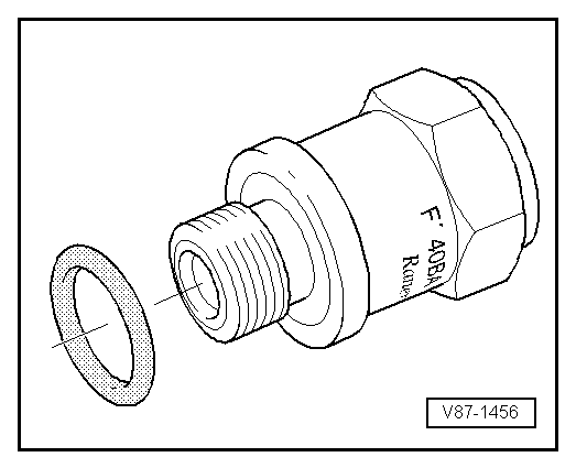
Components of the refrigerant circuit

Caution!
Tools or materials that are not approved (e.g. leak-stop additives) can cause damage or impairment to the system.
Only tools and materials approved by the manufacturer may be used.
If tools or materials that are not approved have been used, there is no warranty.
- All components of the refrigerant circuit that are sent in for quality monitoring must always be sealed (use the original sealing caps of the original part).
- Replace damaged or leaking components of the refrigerant circuit.
- The original parts (A/C compressor, accumulator, receiver/drier, evaporator and condenser) were previously filled with nitrogen gas. This filling is being phased out. Therefore, when unscrewing the sealing plug from the original part, no pressure equalization or only a very slight one is noticeable.
Arrangement of the refrigerant circuit components and their effect on the high and low pressure sides
On the high-pressure side, these are the condenser and the receiver/drier. The orifice tube or expansion valve separates the high-pressure liquid side from the low-pressure liquid side.
High pressure builds up because the orifice tube or expansion valve forms a restriction and the refrigerant backs up, which causes pressure and temperature to rise.
Excessive pressure occurs if too much refrigerant or refrigerant oil is filled in, the condenser is dirty, the radiator fan is faulty, there is a blockage in the system, or moisture is present in the refrigerant circuit (icing of the restrictor or expansion valve).
The low-pressure side contains the evaporator, accumulator, evaporator temperature sensor, and, as the separation between the high-pressure gas side and the low-pressure gas side, the A/C compressor.
Pressure drop in the system can be caused by refrigerant loss, restrictor or expansion valve (no restriction present), faulty A/C compressor, or evaporator icing.
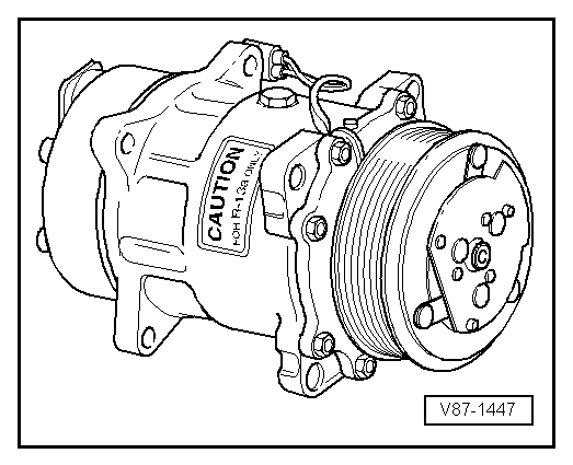
A/C compressor with magnetic clutch:
The A/C compressor is driven by the engine via a V-ribbed belt.
With the air conditioning switched on, an electromagnetic clutch fitted to the A/C compressor creates the frictional connection between the V-ribbed belt pulley and the A/C compressor crankshaft.
A fusible link fitted in the V-ribbed belt pulley of the A/C compressor triggers the electromagnetic clutch if the A/C compressor seizes, and protects the V-ribbed belt drive from overload.
The A/C compressor draws refrigerant gas from the evaporator, compresses it and delivers it to the condenser.

Note
- The A/C compressor contains refrigerant oil that is miscible with R134a refrigerant at all temperatures.
- The type plate indicates the refrigerant for which the A/C compressor is designed. A control valve regulates the pressure on the low-pressure side within the specified setpoint range (control characteristic).
- To prevent damage to the A/C compressor when the refrigerant circuit is empty, the magnetic clutch is switched off and the control valve for A/C compressor -N280- is no longer activated (the A/C compressor runs idle with the engine).
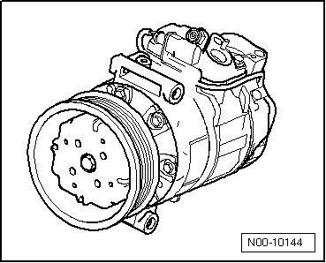
A/C compressor without magnetic clutch
The A/C compressor is driven by the engine via a V-ribbed belt.
An overload protection (shear section) fitted in the V-ribbed belt pulley of the A/C compressor triggers if the A/C compressor seizes, and protects the V-ribbed belt drive from overload.
The A/C compressor draws refrigerant gas from the evaporator, compresses it and delivers it to the condenser.

Note
- The A/C compressor contains refrigerant oil that is miscible with R134a refrigerant at all temperatures.
- The type plate indicates the refrigerant for which the A/C compressor is designed. A control valve regulates the pressure on the low-pressure side within the specified setpoint range (control characteristic).
- On this A/C compressor, the control valve is activated externally.
- The engine should only be started when the refrigerant circuit is fully assembled.
- To prevent damage to the A/C compressor when the refrigerant circuit is empty, it is equipped with a secured oil supply. This means that approx. 40 to 50 cm3 of refrigerant oil remains in the A/C compressor.
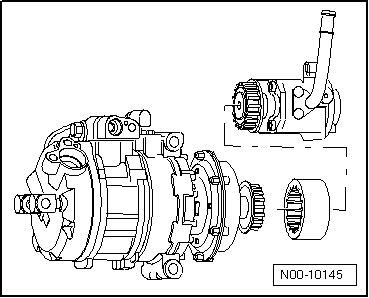
A/C compressor without magnetic clutch, with torsionally elastic coupling
The A/C compressor is driven directly by the power steering vane pump.
A overload protection on the drive shaft of the A/C compressor shears if the A/C compressor seizes, so that the power steering vane pump remains functional.
The A/C compressor draws refrigerant gas from the evaporator, compresses it and delivers it to the condenser.

Note
- The A/C compressor contains refrigerant oil that is miscible with R134a refrigerant at all temperatures.
- The type plate indicates the refrigerant for which the A/C compressor is designed. A control valve regulates the pressure on the low-pressure side within the specified setpoint range (control characteristic).
- On this A/C compressor, the control valve is activated externally.
- The engine should only be started when the refrigerant circuit is fully assembled.
- To prevent damage to the A/C compressor when the refrigerant circuit is empty, it is equipped with a secured oil supply. This means that approx. 40 to 50 cm3 of refrigerant oil remains in the A/C compressor.
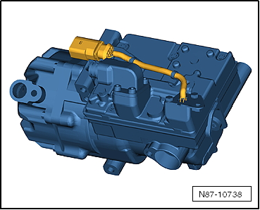
Electrically driven A/C compressor for high-voltage system

WARNING!
- High voltage in the high-voltage system of the hybrid vehicle! Health risk for persons with life-support systems!
- The following work procedure also requires work on the high-voltage system. All work on vehicles with a high-voltage system may only be performed by persons instructed in electrical work. The work must be directed by a high-voltage technician.
- Observe the general warnings for work on the high-voltage system ⇒ Electric drive. General warnings for work on the high-voltage system.
- Establish de-energized state of the high-voltage system now ⇒ Electric drive; Establishing de-energized state of the high-voltage system.

WARNING!
The electrically driven A/C compressor uses a different refrigerant oil!
See vehicle-specific repair manual.
Electrically driven A/C compressor

WARNING!
Risk of short circuit
The A/C compressor operates at 288 volts with a speed range of 800 to 8600 rpm.
Do not touch the A/C compressor when the drive machines are started, risk of short circuit.
The A/C compressor draws refrigerant gas from the evaporator, compresses it and delivers it to the condenser.

Note
- The A/C compressor contains refrigerant oil that is miscible with R134a refrigerant at all temperatures.
- The type plate indicates the refrigerant for which the A/C compressor is designed. The delivery rate is controlled via the speed.
- The engine should only be started when the refrigerant circuit is fully assembled.
- To prevent damage to the A/C compressor when the refrigerant circuit is empty, it is equipped with a secured oil supply. This means that approx. 40 to 50 cm3 of refrigerant oil remains in the A/C compressor.
- The A/C compressor has a pressure relief valve.
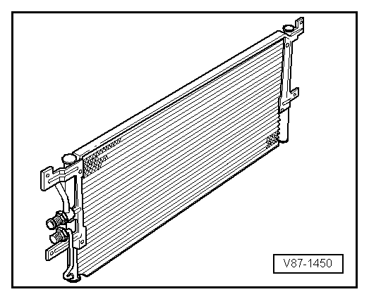
Condenser
The condenser releases heat from the compressed refrigerant gas to the ambient air.
In the process, refrigerant gas condenses into liquid.
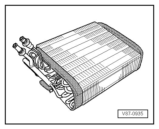
Evaporator
The liquid refrigerant evaporates in the tubes of the evaporator. The heat required for this is drawn from the air flowing past the evaporator fins. The air cools down. The refrigerant evaporates and, with the absorbed heat, is drawn in by the A/C compressor.
A defined quantity of refrigerant is supplied to the evaporator via a restrictor or expansion valve. In systems with an expansion valve, the flow is regulated so that only gaseous refrigerant exits at the evaporator outlet.
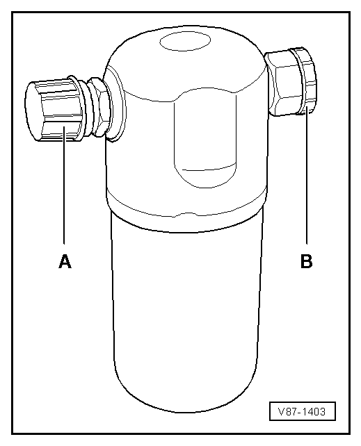
Accumulator
So that the A/C compressor draws in only gaseous refrigerant, the accumulator collects the vapor and gas mixture coming from the evaporator. The vapor becomes gaseous refrigerant.
Refrigerant oil flowing along in the circuit does not remain in the accumulator, because an oil suction bore is provided.
Moisture that has entered the refrigerant circuit during installation is trapped by a filter (desiccant bag) in the container.
Gaseous refrigerant with oil is drawn in by the A/C compressor.

Note
- Replace the accumulator if the refrigerant circuit has been open for a longer time (beyond the normal repair time) and moisture has entered, or if it is specified due to a specific complaint.
- Remove sealing plugs -A- and -B- only shortly before installation.
- If the accumulator is not sealed, the desiccant bag becomes saturated with moisture after a short time and is unusable.
- When installing, observe the arrow for flow direction if applicable.
Restrictor
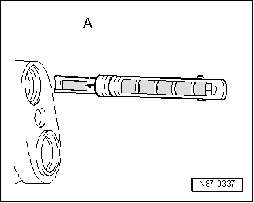
The orifice tube forms a restriction. This restriction throttles the flow and thereby separates the refrigerant circuit into a high-pressure side and a low-pressure side. Upstream of the orifice tube, the refrigerant is warm and under high pressure. Downstream of the orifice tube, the refrigerant is cold and under low pressure. Upstream of the restriction there is a screen against debris; downstream of the restriction there is a screen that atomizes the refrigerant before it enters the evaporator.

Note
- Arrow -A- on the orifice tube points toward the evaporator.
- Always replace after opening the circuit.
- Note different versions.
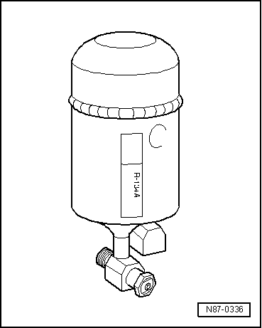
Receiver/drier
The receiver/drier collects liquid refrigerant droplets and then feeds them in a continuous flow to the expansion valve. Moisture that has entered the refrigerant circuit during installation is trapped in the receiver/drier by a desiccant bag.

Note
- Replace the receiver/drier if the refrigerant circuit was open for longer than the normal repair time and moisture has entered, or if it is specified due to a particular complaint.
- Remove the sealing plugs only shortly before installation.
- In a receiver/drier that is not sealed, the desiccant bag becomes saturated with moisture after a short time and is no longer usable.
- When installing, observe the arrow for flow direction if applicable.
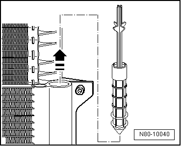
The new generation of receiver/driers is mounted directly on the condenser and contains a desiccant cartridge.

Note
- Replace the desiccant cartridge if the refrigerant circuit was open for longer than the normal repair time and moisture has entered, or if it is specified due to a particular complaint.
- Remove the desiccant cartridge from its packaging only shortly before installation.
- A desiccant cartridge left in unsealed packaging becomes saturated with moisture after a short time and is no longer usable.
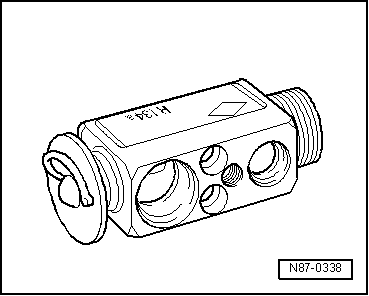
Expansion Valve
The expansion valve atomizes incoming refrigerant and regulates the flow rate so that, depending on the heat transfer, the refrigerant only becomes gaseous at the evaporator outlet.
O-ring
These O-rings seal the connection points between the individual components of the refrigerant circuit.
Only O-rings that are resistant to refrigerant R134a and the associated refrigerant oils may be used. Genuine replacement parts ensure this.
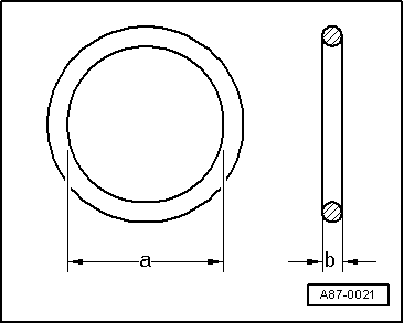
O-ring:
- Use only once.
- Make sure the correct diameters -a- and -b- are used.
- Wet with refrigerant oil before installing.

Note
The color coding of O-rings for refrigerant circuits with R134a no longer applies. Black and colored O-rings are used.
Pipes and hoses of the refrigerant circuit
The mixture of refrigerant oil and refrigerant R134a attacks certain metals (e.g. copper) and alloys and dissolves certain hose materials. Therefore, use genuine replacement parts.
The pipes and hoses are held together by bolted connections or special quick-connect couplings.

Note
Observe the specified torques for bolted connections, and use the specified release tools for quick-connect couplings.
Pressure relief valve
The pressure relief valve is mounted on the A/C compressor or receiver/drier.
At a pressure of approx. 38 bar the valve opens, and it closes again when the pressure has dropped (approx. 30 bar).
The refrigerant does not escape completely.
Depending on the version, a transparent plastic disc may be fitted, which breaks out when the valve responds.