Electrical components not installed in the refrigerant circuit
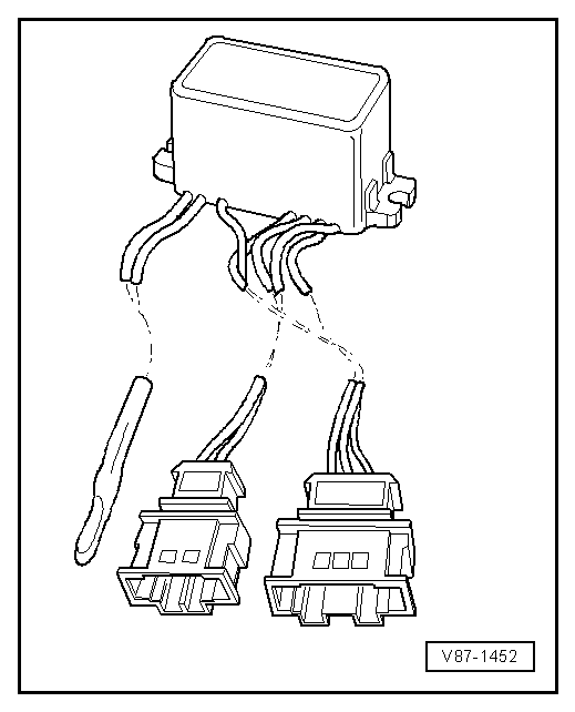
Air conditioning control and regulating unit -J127-
This control and regulating unit shuts off the refrigerant flow through the second evaporator when the temperature on the fins of the second evaporator drops to the freezing point of water (icing protection).
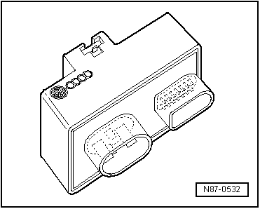
Radiator fan control unit -J293-

Note
Available in different designs, sometimes as a separate unit.
This control unit switches the magnetic clutch and thus the A/C compressor on and off. It switches the radiator fan on and, on vehicles with high-pressure sensor -G65- or refrigerant pressure and refrigerant temperature sensor -G395-, calculates the pressure in the refrigerant circuit.
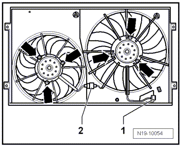
Radiator fan control unit -J293-

Note
Available in different designs, sometimes mounted on the radiator fan -arrows-.
This control unit switches the magnetic clutch and thus the A/C compressor on and off. It switches the radiator fan on and, on vehicles with high-pressure sensor -G65- or refrigerant pressure and refrigerant temperature sensor -G395-, calculates the pressure in the refrigerant circuit.
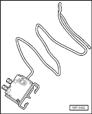
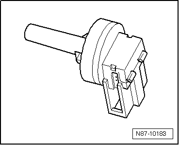
Evaporator temperature switch -E33-
Function:
The evaporator temperature switch -E33- detects the temperature between the evaporator fins. It prevents ice formation between the evaporator fins by interrupting the power supply to the A/C compressor magnetic clutch when the temperature on the fins drops to the freezing point of humidity.
The insertion depth of the sensor tube is marked or specified in the repair manual.

Note
Installed in VW vehicles with the A/C compressor driven by a V-ribbed belt.
Evaporator outlet temperature sensor -G263- or evaporator temperature sensor -G308-
Function:
The evaporator outlet temperature sensor -G263- or evaporator temperature sensor -G308- detects the temperature downstream of the evaporator. This value is sent to the air conditioning control unit and serves as a reference signal for controlling the A/C compressor. This prevents the evaporator from icing up.
Pressures and temperatures in the refrigerant circuit

WARNING!
When working on the refrigerant circuit, observe the generally applicable safety regulations and the pressure vessel regulations.
The pressures and temperatures in the refrigerant circuit depend on current operating conditions (e.g. engine speed, radiator fan stage 1, 2 or 3, engine temperature, A/C compressor on or off) as well as on ambient influences (e.g. ambient temperature, humidity, required cooling capacity).
On vehicles with a control valve for the air conditioning compressor -N280-, the pressure on the low-pressure side is changed by activating the valve.
For this reason, the values given in the following tables can only be used as guide values. They establish themselves after approx. 20 min. at an engine speed of 1500 to 2000 rpm and an ambient temperature of 20 ºC.
The connections provided for pressure measurement for the gauge set can be found in the vehicle-specific refrigerant circuit.
At 20 ºC and with the engine switched off, a pressure of 4.7 bar gauge pressure builds up in the refrigerant circuit.
Refrigerant circuit with expansion valve
- Low-pressure side of the refrigerant circuit.
- High-pressure side of the refrigerant circuit.
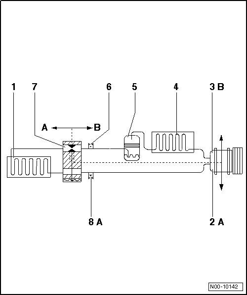
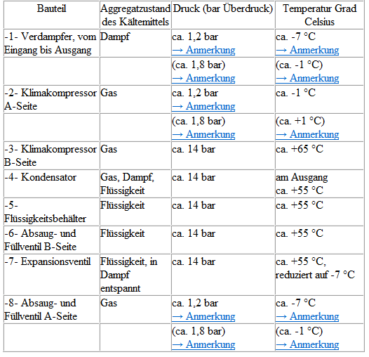
1) In refrigerant circuits with a regulating air conditioning compressor, the pressure is maintained at approx. 2 bar despite changing heat transfer and different engine speeds. However, this only applies within the performance range of the air conditioning compressor; if the performance limits of the air conditioning compressor are exceeded, the pressure rises.
2) In refrigerant circuits with a regulating air conditioning compressor, the temperature is maintained within the control range of the air conditioning compressor despite changing heat transfer and different engine speeds. However, this only applies within the performance range of the air conditioning compressor; if the performance limits of the air conditioning compressor are exceeded, the temperature rises.
3) Measured values for air conditioning systems with two evaporators

Note
- Air conditioning compressors that do not regulate their own output are switched off by the respective control unit via the control valve for the air conditioning compressor -N280- when the evaporator temperature is below 0 ºC.
- On vehicles with a control valve for the air conditioning compressor -N280-, the pressure on the low-pressure side is changed by activating the valve.
Refrigerant circuit with orifice tube and accumulator
Arrows show the direction of refrigerant flow.
- Low-pressure side of the refrigerant circuit.
- High-pressure side of the refrigerant circuit.
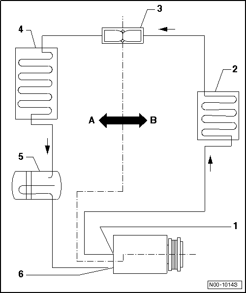
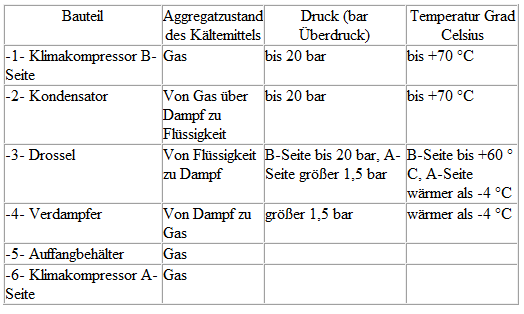
The pressures on the A-side are maintained at approx. 2 bar by the "regulating" air conditioning compressor, even at different engine speeds. However, this only applies within the performance range of the air conditioning compressor, i.e. as long as the performance limits of the air conditioning compressor are not exceeded.

Note
On vehicles with a control valve for the air conditioning compressor -N280-, the pressure on the low-pressure side is changed by activating the valve.