DCT (Dual Clutch Transmission) System
Inhibitor Switch Repair Procedures
In this manual: DCT (Dual Clutch Transmission) System
22steps
~137min
5/5difficulty
1special tools
Done 0 of 22
Inspection
Flow Inspection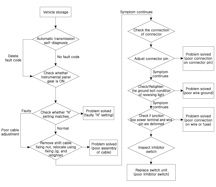
- Check the DTC.
- Check whether the N position setting is correct.
- Adjust the N position setting (refer to "Dual Clutch Transmission Control System"). System: "Inhibitor Switch".
- Check the shift cable separation.
- Adjust the shift cable clearance (refer to "Dual Clutch Transmission"). Control system: "Inhibitor Switch".
- Check whether the connector is connected.
- Carefully inspect the connector for looseness, poor contact, bending, corrosion, contamination, deformation, or damage.
- Turn the ignition ON, turn the engine OFF, and measure the voltage between the shift lock switch circuit and ground.
Specification: Approx. 12 V
- Repair the wiring at the connector terminals if the connector wiring is faulty (refer to ETM - "Wiring Repair").
- Check the ground condition in the back-up lamp circuit.
- Check the back-up lamp ground location (refer to ETM - "Wiring Location Chart").
- Reattach the back-up lamp if the ground condition is not normal.
- Inspect the wire connection at the power terminal of the junction box and the fuse lamp.
- Check whether the fuse holder is separated and whether the fuse holder holds the fuse tightly.
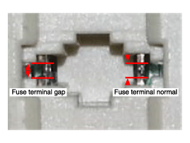
- Attach the tester fuse to check whether it is connected correctly.
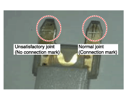
- Check whether the fuse capacity is suitable for each circuit.
- Check whether the fuse is damaged.
- Check the fuse holder wiring for pull-out, foreign material, and terminal location.
- Move the terminal that was pulled out and inspect it using the method described above.
- If the problem is not resolved, refer to the electrical repair instructions to repair or replace the terminal.
- Check whether the fuse holder is separated and whether the fuse holder holds the fuse tightly.
- Check the shift lock switch signal.
- Turn the ignition switch to the "ON" position and the engine "OFF".
- Measure the voltage between each terminal and chassis ground while moving the shift lever into the "P, R, N, D" ranges.
Specified value: Refer to the "Signal Code" specification table.
Removal
- Before moving the shift lever to the "N" position, make sure the vehicle is not rolling.
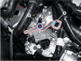
- Disconnect the shift lock switch connector (A).
- Remove the shift cable mounting nut (B).
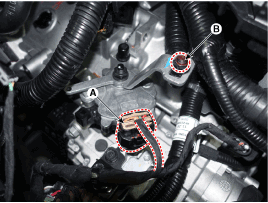
- Remove the shift lever handle (A) after loosening the nuts (B).
- Remove the shift lock switch (A) after loosening the bolts (B-2EA).
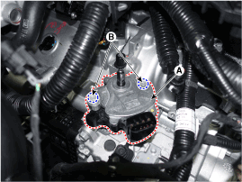
Installation
- Make sure the shift lever is in the "N" position.
- After installation, lightly tighten the shift lock switch mounting bolts (B-2EA) to the shift lock switch (A).
- After installing the shift lever handle (A), tighten the shift lever handle mounting nut (B) to the specified torque.
Tightening torque: (B) 17.4–24 N·m
- Align the hole (B) in the shift lever handle with the "N" position hole (A) of the shift lock switch, then insert the shift lock switch guide pin (SST No.: 09480-A3800) into the corresponding hole.
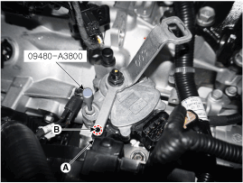
- Tighten the bolt (A) to the specified torque.
Tightening torque: (A) 9.8–11.8 N·m
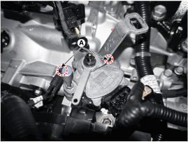
- Lightly tighten the nut (B) after connecting the shift cable (C) to the shift lever (D).
- Lightly push the shift cable (C) in the direction shown by arrow "F" to remove the free play from the shift cable. Tighten the nut (B) to the specified torque.
Tightening Torque: 9.8–13.7 N·m
- Connect the shift lock switch connector (A).
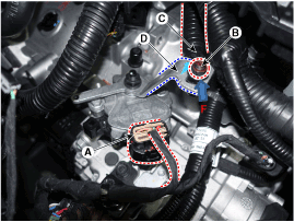
- Remove the shift lock switch guide pin (SST No.: 09480-A3800) from the hole.
- Install the air cleaner assembly and air duct. (Refer to Engine Mechanical System - "Air Cleaner".)
Test yourself
A quick Hyundai Kona quiz: every answer comes with an explanation and a link to the manual page.
Was this page helpful?