Ventilated Seat
Components and Component Location
Components
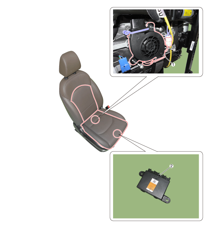
| 1. Fan | 2. Ventilated Seat (Passenger Seat Only) |
Circuit Diagrams
Connector and Terminal Function
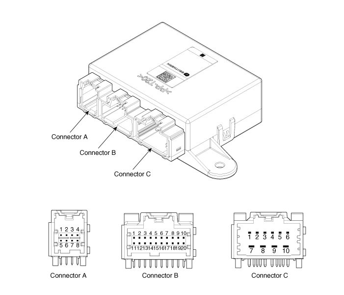
| No. | Connector A | Connector B | Connector C |
| 1 | Driver's Seat Ventilation Switch | NTC (-) | Driver's Seat Cushion Heater Output |
| 2 | Passenger's Seat Ventilation Switch | Right Seat Heater Indicator (High) | Driver's Seat Back Heater Output |
| 3 | Passenger's Seat Ventilation Indicator (High) | Left Seat Heater Indicator (Low) | Passenger's Seat Cushion Heater Output |
| 4 | Driver's Seat Ventilation Indicator (Low) | Right Seat Heater Switch | Passenger's Seat Back Heater Output |
| 5 | Passenger's Seat Fan Speed | Right Seat Heater Indicator (Low) | Driver's Seat Fan Output |
| 6 | Driver's Seat Fan Speed | Right Seat Heater Indicator (Medium) | Passenger's Seat Fan Output |
| 7 | Driver's Seat Ventilation Indicator (Medium) | - | Battery (+) |
| 8 | Driver's Seat Ventilation Indicator (High) | Illumination (-) | Driver's Seat Heater Ground |
| 9 | Latch | Ground | |
| 10 | Ventilation/Heater Unit_IGN 1 | Passenger's Seat Heater Ground | |
| 11 | - | ||
| 12 | Driver's Seat Heater Indicator (Medium) | ||
| 13 | Driver's Seat Heater Indicator (High) | ||
| 14 | Driver's Seat Heater Switch | ||
| 15 | Passenger's Seat Ventilation Indicator (Low) | ||
| 16 | Passenger's Seat Ventilation Indicator (Medium) | ||
| 17 | - | ||
| 18 | Right Seat NTC (+) | ||
| 19 | Driver's Seat NTC (+) | ||
| 20 | Ventilation/Heater Unit_IGN 2 |
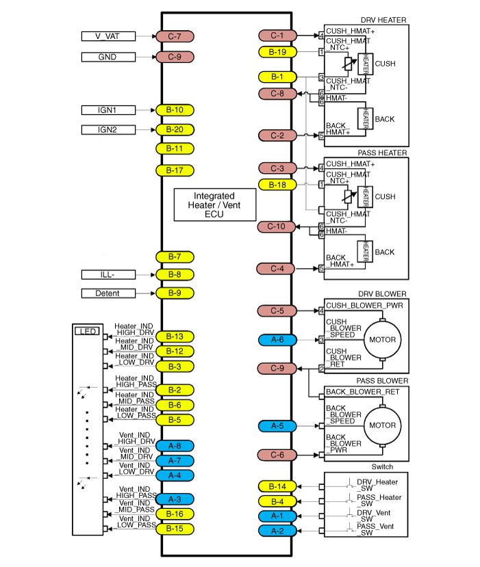
Wiring Diagram
Repair Procedures
Inspection
The ventilated seat consists of three components: the ventilated seat control unit, the input switch, and the output fan.
You can enter diagnostic mode by pressing the seat heater button.
You can enter diagnostic mode by referring to the following description.
Press the heating wire switch as shown below.
Press and hold the heating wire switch for at least 3 seconds.
Release the switch for 3 seconds or less, then press and hold it again for 1.5 - 3 seconds.
Release the switch for 3 seconds or less, then press and hold it again for 3 seconds or more.
After entering diagnostic mode, check the LED status to identify the fault.
[Heater]
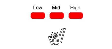
Failure Indicator Failure Items Failure Details Low: Flashing
Medium: Flashing
High: ONLow Voltage Detection - IGN 1 Power 8.5 V or less Overvoltage Detection - IGN 1 Power 16.5 V or more Low: OFF
Medium: Flashing
High: ONFuse (Short) - IGN2 fuse open Low: OFF
Medium: ON
High: FlashingNTC/HEATING MAT (Disconnected) - NTC element failure
- Cushion/rear heating mat disconnected
- NTC (+) wiring disconnected
- NTC (-) wiring disconnected
- Heater (+) wiring open
- Heater (-) wiring openLow: Flashing
Medium: ON
High: OFFNTC/HEATING MAT (Short) - Short circuit between controller connector terminal and heater
- Short circuit in heater system NTC (+) wiring
- Short circuit in heater system NTC (-) wiring
- Short circuit in heater system heater (+) wiring
- Short circuit in heater system heater (-) wiringLow: Flashing
Medium: ON
High: FlashingTarget temperature not reached - Target temperature not reached within 40 minutes
[Ventilation System]
Failure Indicator Failure Items Failure Details Low: ON
Medium: Flashing
High: ONShort in ventilation fan power supply line - Short circuit of ventilation fan power/ground line
- Short circuit of ventilation fan power line to B(+)Low: ON
Medium: OFF
High: FlashingVentilation fan power open
Ventilation fan speed signal open- Ventilation fan power open
- Ventilation fan ground (GND) open
- Ventilation fan speed signal openLow: Flashing
Medium: Flashing
High: OFFShort in ventilation fan speed signal - Short circuit of ventilation fan speed signal line to power
- Short circuit of ventilation fan speed signal to GND
- Short circuit of ventilation fan speed signal to fan speed signalLow: OFF
Medium: Flashing
High: FlashingOpen or disconnected ventilation fan speed signal connector - Ventilation fan speed signal connector disconnected or missing Low: Flashing
Medium: OFF
High: FlashingVentilation fan speed signal short circuit - Short circuit of fan speed signal line to power
- Short circuit of ventilation fan speed signal to GNDYou can check for a failure by observing the LED blinking pattern.
Malfunction data is stored in the memory of the ventilated seat unit.
Press and hold the passenger seat heater switch for at least 5 seconds. The LED will flash four times and the malfunction data in memory will be erased.
Turning the ignition OFF will end the seat heater diagnostic mode.
You can check whether the seat heater system operates correctly by turning the ignition ON. To check the trouble code, refer to procedure 2 above.
Removal
Ventilated Seat
Remove the heater unit.
(Refer to Seat Electrical - "Seat Heater Unit")
Seat Ventilation
Disconnect the negative (-) battery terminal.
Remove the driver/passenger seat assembly.
(Refer to Body - "Front Seat Assembly")
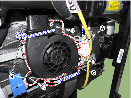
Remove the fan (C) by loosening the screws and clips (B) after disconnecting the connector (A).
Installation
Install in the reverse order of removal.
Test yourself
A quick Kia Forte BD quiz: every answer comes with an explanation and a link to the manual page.