Compressor
Description and Operation
Description
The compressor is the power unit of the air conditioning system.
It is located on the side of the cylinder block and is driven by the engine drive belt.
The compressor converts low-pressure, low-temperature gaseous refrigerant into high-pressure, high-temperature gaseous refrigerant.
Variable Displacement Swash Plate Compressor
The compressor has a swash plate that rotates to reciprocate the pistons, which compress the refrigerant.
The variable displacement swash plate compressor adjusts the swash plate angle to change refrigerant displacement. It provides precise control of cooling capacity according to the vehicle interior and driving conditions.
The externally controlled variable displacement compressor changes the swash plate angle using the ECV (Electronic Control Valve) according to the electrical signal from the heater and air conditioner control unit.
This provides stable temperature control and improves driving comfort.
ECV Control Circuit
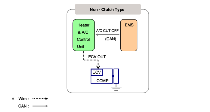
Components and Component Location
Components
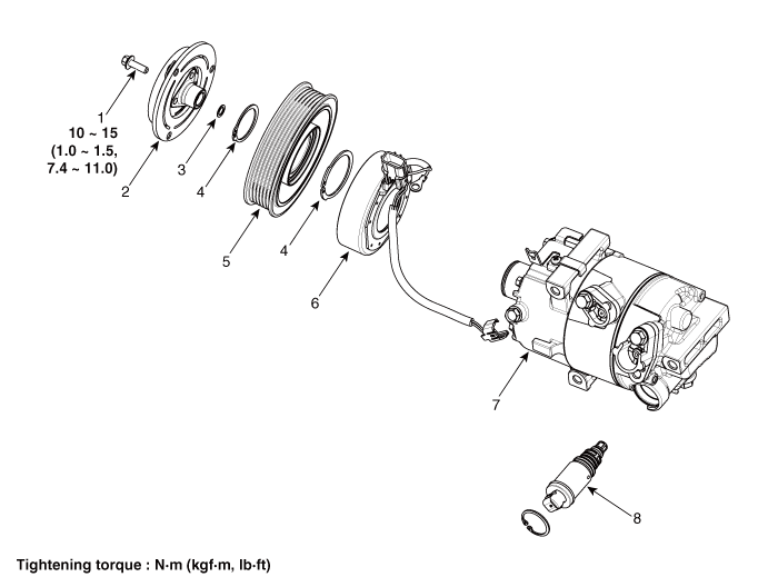
| 1. Clutch Bolt 2. Stopper and Hub Assembly 3. Compressor Spacer 4. Snap Ring |
5. Pulley 6. Field Coil Assembly 7. Compressor Assembly 8. Electronic Control Valve (ECV) |
Repair Procedures
Removal
If the compressor is operating at its limit, run the engine at idle and let the air conditioner operate for several minutes, then stop the engine.
Disconnect the negative (-) battery terminal.
Recover the refrigerant using a recovery/recharging station.
Remove the engine room cover.
G 2.0 MPI NU (Refer to Engine Mechanical System - Engine Room Under Cover)
G 1.6 MPI GAMMA (Refer to Engine Mechanical System - Engine Room Under Cover)
D 1.6 TCI-NEW U (Refer to Engine Mechanical System - Engine Room Under Cover)
G 1.6 T-GDI GAMMA (Refer to Engine Mechanical System - "Engine Room Cover")
Loosen the drive belt.
G 2.0 MPI NU (Refer to Engine Mechanical System - Drive Belt)
G 1.6 MPI GAMMA (Refer to Engine Mechanical System - Drive Belt)
D 1.6 TCI-NEW U (Refer to Engine Mechanical System - Drive Belt)
G 1.6 T-GDI GAMMA (Refer to Engine Mechanical System - Drive Belt)
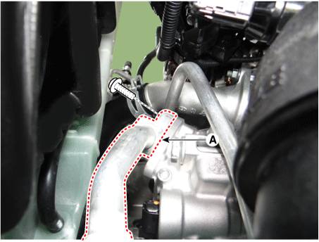
Remove the bolts, then disconnect the discharge line (A) from the compressor.
Tightening Torque: 21.6–32 N·m
Remove the bolts, then disconnect the suction line (A) from the compressor.
Tightening Torque: 21.6–32 N·m
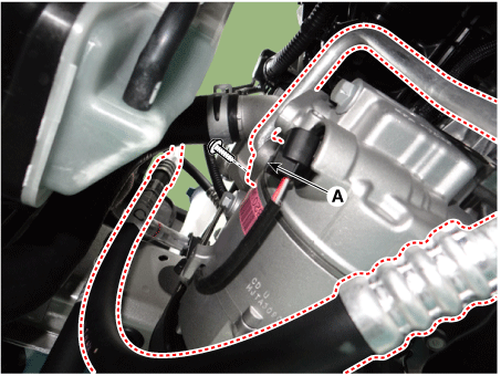
Disconnect the compressor switch connector (A).
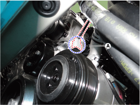
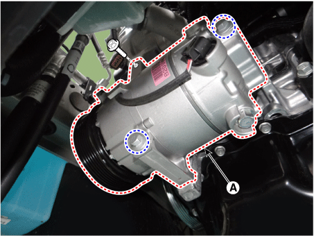
Remove the compressor (A) by loosening the mounting bolts.
Tightening torque: 19.6 - 33 N·m
Installation
Make sure the compressor mounting bolts of the correct length are tightened. Tighten the mounting bolts in the specified order.
Tightening torque: 19.6 - 33 N·m
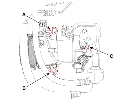
To install, reverse the removal procedure.
Inspection
Inspect the limiter and hub for discoloration, peeling, or other damage. If damaged, replace the assembly.
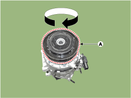
Check the clearance of the pulley bearing (A) and rotate the pulley by hand. Replace the pulley if it is noisy or has excessive play/drag.
Inspection of Compressor with External Control Valve (ECV)
Compressor Type: Fixed-type compressor, External control valve, Internal control valve.
For the fixed type and internal control valve type, the compressor operation can be checked by the clutch engagement sound.
However, for the external control valve type, it cannot be checked this way because it does not have a clutch.
Therefore, the ECV should be checked using the KDS as shown below.
Connect the KDS to the vehicle and select "A/C Compressor Test (ECV Type)".
[ECV1]
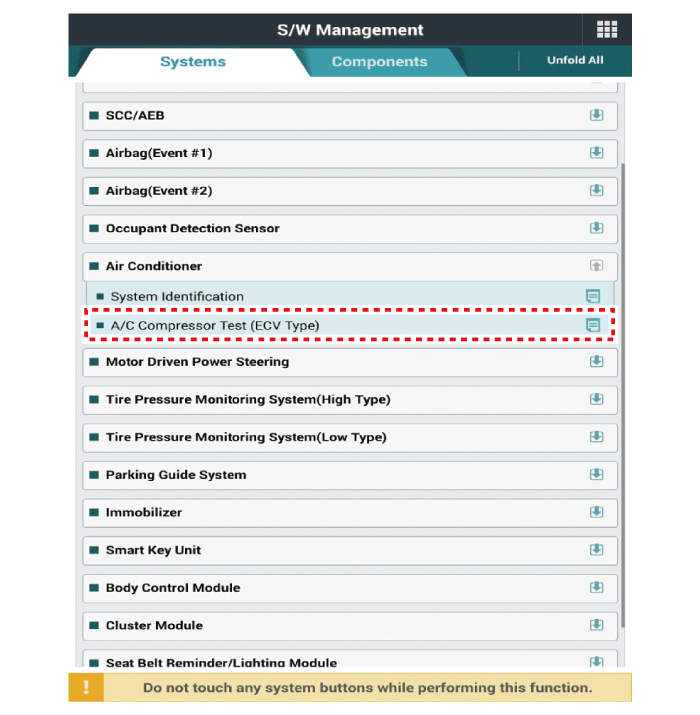
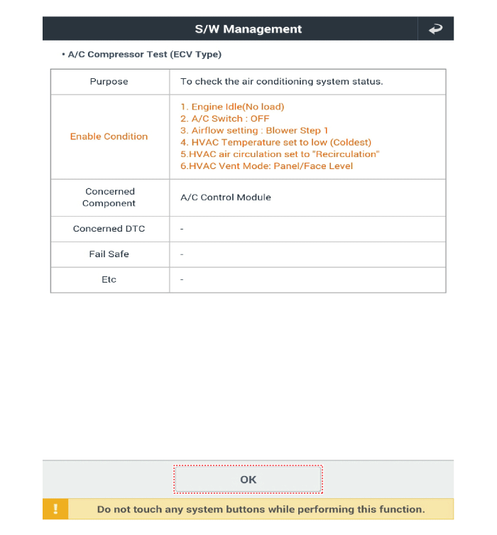
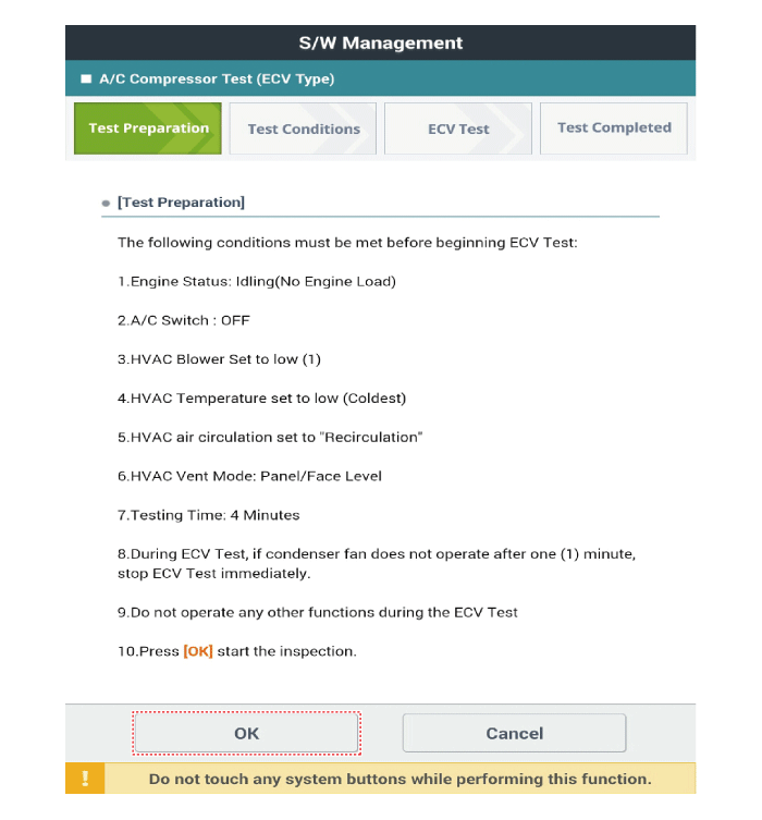
Prepare the vehicle according to the KDS instructions on the monitor. (Turn off only the A/C switch)
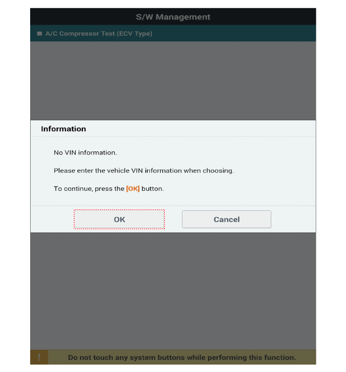
Before inspecting the ECV compressor, check whether other DTCs are present. If so, resolve those issues first. If not, press the "OK" button to continue.
Start Inspection
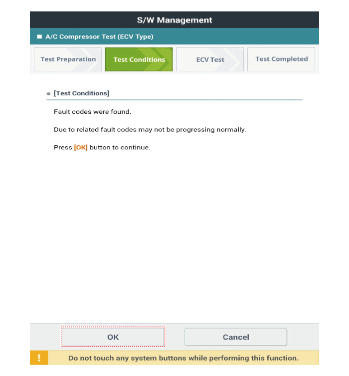
Check the inspection result.
[ECV7]
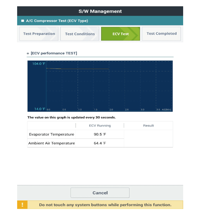
[ECV8]
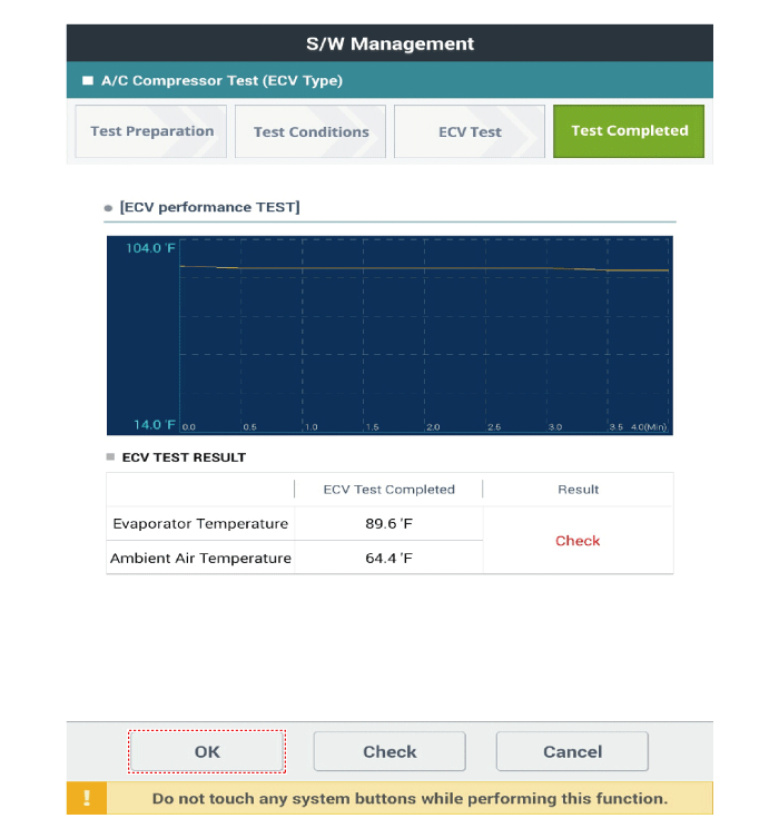
If the result displays "Check", press "Check" and follow the instructions.
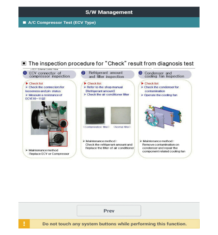
Recheck the ECV from the first step.
Disassembly
Remove the engine room cover.
G 2.0 MPI NU (Refer to Engine Mechanical System - Engine Room Under Cover)
G 1.6 MPI GAMMA (Refer to Engine Mechanical System - Engine Room Under Cover)
D 1.6 TCI-NEW U (Refer to Engine Mechanical System - Engine Room Under Cover)
G 1.6 T-GDI GAMMA (Refer to Engine Mechanical System - "Engine Room Cover")
Loosen the drive belt.
G 2.0 MPI NU (Refer to Engine Mechanical System - Drive Belt)
G 1.6 MPI GAMMA (Refer to Engine Mechanical System - Drive Belt)
D 1.6 TCI-NEW U (Refer to Engine Mechanical System - Drive Belt)
G 1.6 T-GDI GAMMA (Refer to Engine Mechanical System - Drive Belt)
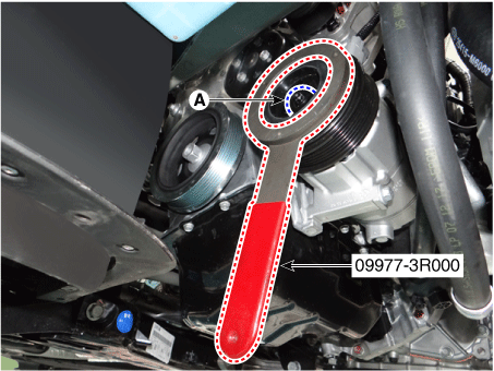
Remove the clutch bolt while holding the pulley with the clutch bolt wrench (09977-3R000).
Tightening torque: 9.8 ~ 14.7 N·m
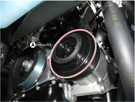
Loosen the limiter bolts, then remove the limiter and hub assembly (A).
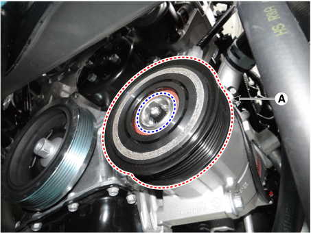
Remove the pulley (A) after first removing the snap ring using snap ring pliers.
Assemble in the reverse order of disassembly.
Clean the sliding surfaces of the pulley and compressor with non-oil solvent.
Install a new snap ring and make sure it is fully seated in the groove.
Make sure the pulley rotates smoothly after assembly.
Test yourself
A quick Kia Forte BD quiz: every answer comes with an explanation and a link to the manual page.