Heating,Ventilation And Air Conditioning
Description and Operation
In this manual: Heating,Ventilation And Air Conditioning
119steps
~719min
5/5difficulty
1special tools
Done 0 of 119
Contents:
General Safety Information and Caution ➤
Description and Operation
Description and Operation
The component of the air conditioner is basically as shown in the figure below. As the refrigerant circulates between each part, it continuously changes to liquid → gas → liquid, creating a cooling effect.
|
Refrigerant Recovery/Recycling/Charging/Vacuum/Leak Test
Refrigerant Recovery/Recycling/Charging/Vacuum (R-1234yf)
Equipped with R-1234yf recovery/recycling/charging equipment- Connect the R-1234yf recovery/recycling/charging equipment to the high-pressure service port (A) and low-pressure service port (B) by reading the refrigerant recovery/recycling/charging equipment instruction manual.
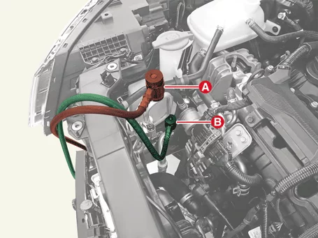
Refrigerant charging equipment should be installed on a flat surface so that it is easy to recover the refrigerant and in particular, the refrigerant can be accurately injected.
- With the high and low pressure valves open, the refrigerant is recovered by using R-1234yf recovery/recycling/charging equipment.
- Refrigerant recovery too quickly causes compressor oil to drain from the system.
- Never disconnect the air conditioning system until the refrigerant has been completely recovered. If it is separated before the recovery of the refrigerant is completed, the refrigerant and oil are discharged into the vehicle by the pressure in the air conditioner system, which causes contamination.
- Refrigerant recovery must be performed with the high and low pressure valves opened. If only one valve is opened, the refrigerant recovery time increases.
- Measure the amount of compressor oil drained from the air conditioner system after the recovery operation is completed. Supplement the compressor oil drained when charging the air conditioner refrigerant.
|
- Perform the vacuum by using R-1234yf recovery/recycling/charging equipment while the high and low pressure valves open.
- If the gauge remains in the vacuum zone for 10 minutes while the high and low pressure valves closed, vacuum has been performed normally. If the pressure increases, it is a leak in the system, so repair the leak by the following order.
- Charging the system with refrigerant charging equipment. (Refer to Refrigerant charging)
- Check the refrigerant leak with leak detector and repair if leak is found. (Refer to Refrigerant leak test)
- Drain the refrigerant again and evacuate the system.
- After evacuating for more than 10 minutes, check the vacuum and close both high and low pressure valves. This state is ready for charging.
Compressor oil must be applied to the O-ring when assembling air conditioner parts, and cleanliness must be maintained to avoid foreign substances, especially gloves. - Replenish the amount of discharged compressor oil by using R-1234yf recovery/recycling/charging equipment while the high pressure valve is opened after evacuating the air conditioner system.
If additional oil is not added when charging the refrigerant, the lubricity deteriorates due to insufficient oil in the system, which cause problem such as compressor sticking. - Charge the refrigerant with specified amount while the high-pressure valve open by using the R-1234yf recovery/recycling/charging equipment and then close the high-pressure valve.
Regulated refrigerant amount : 450 ± 25 g (15.9 ± 0.88 oz.)
Do not overcharge the refrigerant as there is a risk of damage to the compressor. - Check that the refrigerant is not leaking from the system with leak detector. (Refer to refrigerant leak test)
- Check the torque of the connection part, and if it is too loose, check the gas leak with leak detector after tightening it to the specified tightening torque.
- If leakage continues even after re-tightening the connection part, drain the refrigerant and separate the connection part to check the contact surface for damage. If there is even a small damage, replace it with a new one.
- Check the compressor oil and add oil if necessary.
- Charging the system and check for gas leakage. If there is no problem, evacuate the system before charging.
Components and Components Location
Component
G 1.6 T-GDI GAMMA II
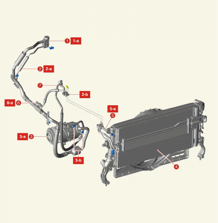
| 1. Expansion Valve 1-a. 8.8 - 13,7 N·m 2. Suction & Liquid Hose Assembly 2-a. 7.8 - 11,8 N·m 2-b. 19.6 - 24 N·m 3. Compressor 3-a. 19.6 - 33 N·m 3-b. 19.6 - 24 N·m 4. Condenser |
5. Condenser Pipe 5-a. 8.8 - 13,7 N·m 6. A/C Pressure Transducer 6-a. 9.8 - 11,8 N·m 7. Discharge Hose Assembly |
G 2.0 MPI NU
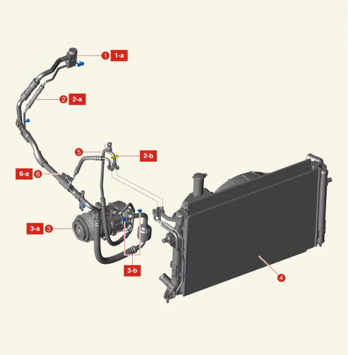
| 1. Expansion Valve 1-a. 8.8 - 13,7 N·m 2. Suction & Liquid Hose Assembly 2-a. 7.8 - 11,8 N·m 2-b. 19.6 - 24 N·m 3. Compressor 3-a. 19.6 - 33 N·m 3-b. 19.6 - 24 N·m |
4. Condenser 5. Discharge Hose Assembly 6. A/C Pressure Transducer 6-a. 9.8 - 11,8 N·m |
On Vehicle Inspection
On Vehicle Inspection
Diagnosis with KDS
- The heating,ventilation and air conditioning system can be more quickly diagnosed for problems with the KDS (Refer to "DTC guide").
- Self diagnosis : Inspect the Diagnostic Trouble Code (DTC) with the KDS. (Refer to DTC guide when fault code is found.)
Refer to the KDS screen for operating conditions and details.
Compressor Oil Inspection
Oil inspection
Oil is used to lubricate the compressor. Since the oil circulates into the system during operation of the compressor, the oil must be replenished to maintain the total amount of the original oil when replacing the parts in the system or when a large amount of gas is leaked.Total amount of oil in the system : TOTAL Planetelf PAG K 30, 120 ± 10g (4.23 ± 0.35 oz.)
- Oil handling tips
- Prevent moisture, dust and metal particles from entering the oil.
- Do not mix oil.
- If the oil is left in the air for a long time after using it, the oil absorbs moisture, so be sure to close the container immediately after use.
- Oil return operation When checking and adjusting the oil level, set the control set to maximum cooling, maximum blower speed and allow the engine to idle for 20 to 30 minutes to restore oil to the compressor.
- Before putting oil into the compressor in use, the compressor oil must be checked in the following order.
- Stop the engine after performing the oil return operation, drain the refrigerant and then remove the compressor from the vehicle.
- Drain the oil from the air conditioning system line connection part.
It is often difficult to drain the oil when the compressor is cooled. In this case, heat the compressor a little (about 40 - 50 °C) before draining the oil. - Measure the amount of drained oil. If the capacity of less than 70 cc (2.37 oz.), the oil has leaked, so perform a leak test at the connection part of each system and repair or replace the defective part if necessary.
- Adjust the oil level after checking the oil for contamination.
Amount of drained oil Adjustment method 70 cc (2.37 oz.) or above Since the oil level is normal, add the amount of oil drained. Below 70 cc (2.37 oz.) Since the oil level is low, fill it up to 70 cc (2.37 oz.).
- Oil filling when replacing the parts.
- Oil replenishment is performed according to the weight difference between the old and new parts.
|
Refrigerant Line Removal and Installation
Removal
Suction & Liquid Hose Assembly[G 1.6 T-GDI GAMMA II]
- If the compressor is operable, run the engine at idle speed, and let the air conditioner operates for a few minutes, then shut the engine off.
- Disconnect the battery negative ( - ) terminal.
- Recover the refrigerant with Recovery/Recycling/Charging equipment. (Refer to Air conditioning System - "Refrigerant Recovery/Recycling/Charging/Vacuum/Leak Test")
- Remove the engine room under cover. (Refer to Engine Mechanical System - "Engine Room Under Cover")
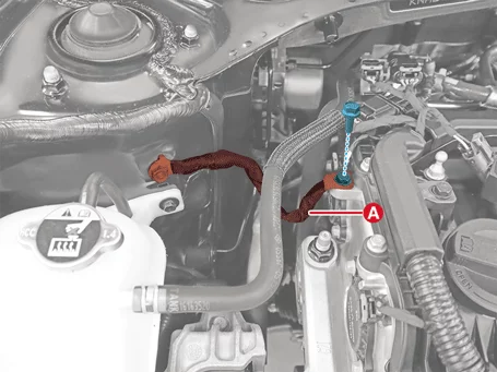
- Separate the engine ground cable (A) after removing the bolt.
Tightening torque : 10.8 - 13,7 N·m
- Remove the engine mounting bracket. (Refer to Engine Mechanical System - "Engine Mounting")
- Remove the expansion valve cover (A) after removing the nut.
Tightening torque : 8.8 - 13,7 N·m

- Remove the expansion valve (A) from the evaporator core after removing the bolts.
Tightening torque : 8.8 - 13,7 N·m

- Disconnect the A/C pressure transducer connector (A).
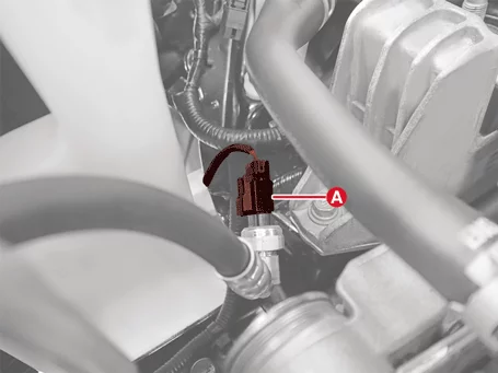
- Separate the suction & liquid hose assembly (A) after removing the nut.
Tightening torque : 19.6 - 24 N·m
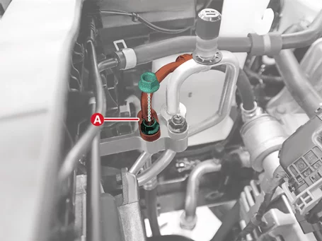
- Separate the suction & liquid hose assembly (A) after removing the bolt.
Tightening torque : 19.6 - 24 N·m
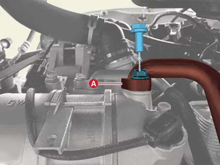
- Remove the suction & liquid hose assembly (A) after removing the bolt and nut.
Tightening torque : 7.8 - 11,8 N·m

[G 2.0 MPI NU]
- If the compressor is operable, run the engine at idle speed, and let the air conditioner operates for a few minutes, then shut the engine off.
- Disconnect the battery negative ( - ) terminal.
- Recover the refrigerant with Recovery/Recycling/Charging equipment. (Refer to Air conditioning System - "Refrigerant Recovery/Recycling/Charging/Vacuum/Leak Test")
- Remove the engine room under cover. (Refer to Engine Mechanical System - "Engine Room Under Cover")
- Remove the engine mounting bracket. (Refer to Engine Mechanical System - "Engine Mounting")
- Remove the expansion valve (A) from the evaporator core after removing the bolts.
Tightening torque : 8.8 - 13,7 N·m
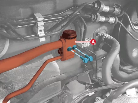
- Disconnect the A/C pressure transducer connector (A).
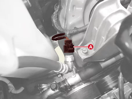
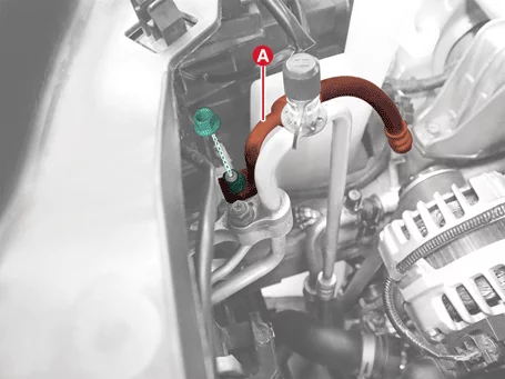
- Remove the suction & liquid hose assembly (A) after removing the nut.
Tightening torque : 19.6 - 24 N·m
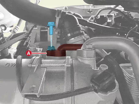
- Disconnect the suction & liquid hose assembly (A) after removing the bolt.
Tightening torque : 19.6 - 24 N·m

- Separate the engine ground cable (A) after removing the bolt.
Tightening torque : 10.8 - 13,7 N·m

- Remove the suction & liquid hose assembly (A) after removing the bolt and nut.
Tightening torque : 7.8 - 11,8 N·m

[G 1.6 T-GDI GAMMA II]
- If the compressor is operable, run the engine at idle speed, and let the air conditioner operates for a few minutes, then shut the engine off.
- Recover the refrigerant with Recovery/Recycling/Charging equipment. (Refer to Air conditioning System - "Refrigerant Recovery/Recycling/Charging/Vacuum/Leak Test")
- Remove the engine room under cover. (Refer to Engine Mechanical System - "Engine Room Under Cover")
- Remove the discharge hose (A) after removing the bolt and nut.
Tightening torque : 19.6 - 24 N·m
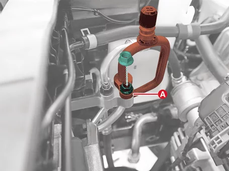
[G 2.0 MPI NU]
- If the compressor is operable, run the engine at idle speed, and let the air conditioner operates for a few minutes, then shut the engine off.
- Recover the refrigerant with Recovery/Recycling/Charging equipment. (Refer to Air conditioning System - "Refrigerant Recovery/Recycling/Charging/Vacuum/Leak Test")
- Remove the engine room under cover. (Refer to Engine Mechanical System - "Engine Room Under Cover")
- Remove the discharge hose (A) after removing the bolt and nut.
Tightening torque : 19.6 - 24 N·m
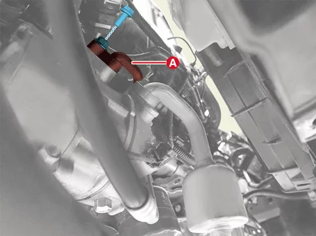
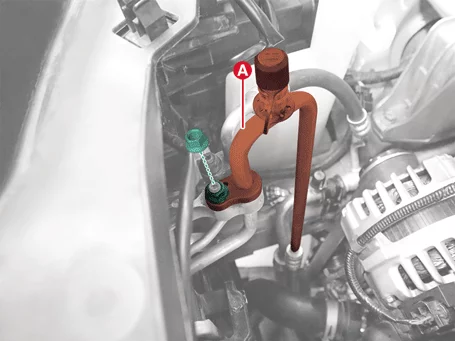
Installation
- Install in reverse order of removal.
- Perform refrigerant leak Test / vacuum / charging. (Refer to Air conditioning System - "Refrigerant Recovery/Recycling/Charging/Vacuum/Leak Test")
- Perform the compressor oil inspection. (Refer to Air conditioning System - "Compressor Oil")
Compressor Description and Operation
Description
The compressor is the power unit of the air conditioning system, mounted on the side of the engine block and driven by the engine drive belt. The compressor changes the low pressure and low temperature refrigerant to high pressure and high temperature.Compressor Removal and Installation
Removal
[G 1.6 T-GDI GAMMA II]- Disconnect the battery negative ( - ) terminal.
- Recover the refrigerant with Recovery/Recycling/Charging equipment. (Refer to Air conditioning System - "Refrigerant Recovery/Recycling/Charging/Vacuum/Leak Test")
- Remove the engine room under cover. (Refer to Engine Mechanical System - "Engine Room Under Cover")
- Remove the drive belt.[G 1.6 T-GDI GAMMA II] (Refer to Engine Mechanical System - "Drive Belt")
- Separate the suction & liquid hose assembly (A) after removing the bolt.
Tightening torque : 19.6 - 24 N·m
- Separate the discharge hose assembly (A) after removing the bolt.
Tightening torque : 19.6 - 24 N·m

- Disconnect the compressor ECV connector (A).
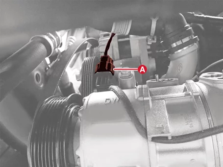
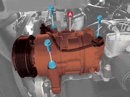
- Remove the compressor assembly (A) after removing the bolts.
Tightening torque : 19.6 - 33 N·m
- Disconnect the battery negative ( - ) terminal.
- Recover the refrigerant with Recovery/Recycling/Charging equipment. (Refer to Air conditioning System - "Refrigerant Recovery/Recycling/Charging/Vacuum/Leak Test")
- Remove the engine room under cover. (Refer to Engine Mechanical System - "Engine Room Under Cover")
- Remove the drive belt.[G 2.0 MPI NU] (Refer to Engine Mechanical System - "Drive Belt")
- Disconnect the suction & liquid hose assembly (A) after removing the bolt.
Tightening torque : 19.6 - 24 N·m

- Disconnect the discharge hose assembly (A) after removing the bolt.
Tightening torque : 19.6 - 24 N·m
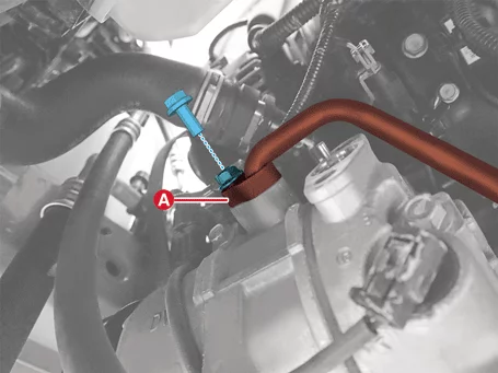
- Disconnect the compressor ECV connector (A).

- Remove the compressor assembly (A) after removing the bolts.
Tightening torque : 19.6 - 33 N·m

Installation
- Install in reverse order of removal.
- Perform refrigerant leak Test / vacuum / charging. (Refer to Air conditioning System - "Refrigerant Recovery/Recycling/Charging/Vacuum/Leak Test")
- Perform the compressor oil inspection. (Refer to Air conditioning System - "Compressor Oil")
Compressor Inspection
Inspection
Visual Inspection- Check for damage to the disc portion of the disc and hub assembly. If there is any damage, replace the clutch set.
- Check the pulley (A) bearing play / drag by rotating the pulley by hand. Replace the pulley with a new one if it is noisy or has excessive play / drag.
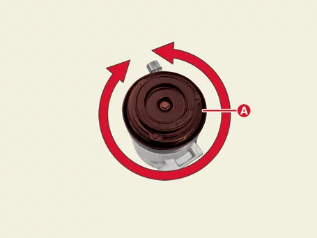
- "A/C Compressor test (ECV type)" is performed using KDS. (S/W Management → Air conditioning → A/C Compressor Test (ECV Type))
Refer to the KDS screen for operating conditions and details.
Compressor Disassembly and Reassembly
Special Service Tool
| Tool Name / Number | Illustration | Description |
| 09977 - 3R000 Disc & hub assembly bolt stopper |
 |
Used to fixing air conditioner compressor disc and hub assembly (G 2.0 MPI NU) |
| 09977 - B9100 Disc & hub assembly bolt stopper |
 |
Used to fixing air conditioner compressor disc and hub assembly (G 1.6 T-GDI GAMMA II) |
Disassembly
[G 1.6 T-GDI GAMMA II]- Remove the front wheel guard [Passenger's side]. (Refer to Body - "Front Wheel Guard")
- Remove the drive belt. [G 1.6 T-GDI GAMMA II] (Refer to Engine Mechanical System - "Drive Belt")
- Fix the disk and hub assembly using the air conditioner compressor pulley fixing tool (09977-3R000) (B) and removing the central bolt (A).
Tightening torque : 14.7 - 21 N·m
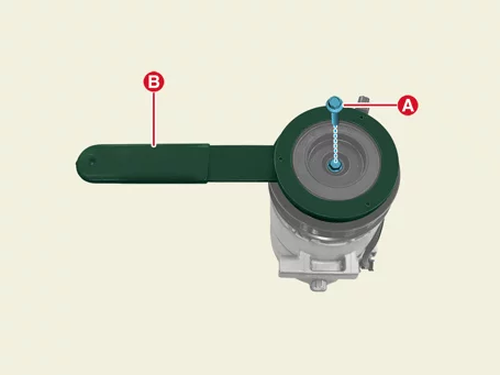
- Remove the disc and hub assembly (A) by using the remover.
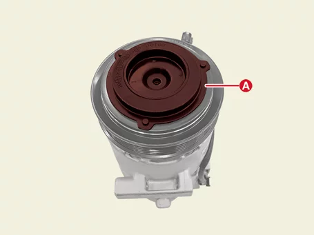
- Remove the compressor pulley (B) after removing the snap ring (A) by using the snap ring plier.
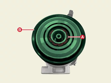
- Disconnect the ECV connector (A) and remove the stator ground screw (B).
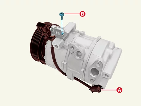
- Remove the stator assembly (B) after removing the snap ring (A) by using the snap ring plier.
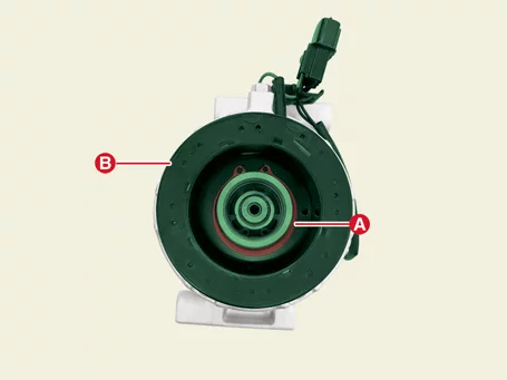
- Remove the front wheel guard [Passenger's side]. (Refer to Body - "Front Wheel Guard")
- Remove the drive belt. [G 2.0 MPI NU] (Refer to Engine Mechanical System - "Drive Belt")
- Fix the disk and hub assembly using the air conditioner compressor pulley fixing tool (09977-3R000) (B) and removing the central bolt (A).
Tightening torque : 14.7 - 21 N·m
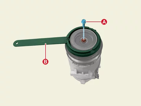
- Remove the disc and hub assembly (A) by using the remover.
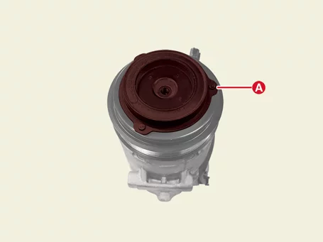
- Remove the compressor pulley (B) after removing the snap ring (A) by using the snap ring pliers.
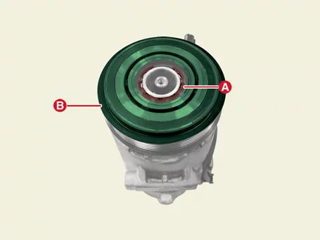
- Be careful not to damage the pulley and compressor when disassembling/assembling.
- Removed snap rings must be replaced with new ones.
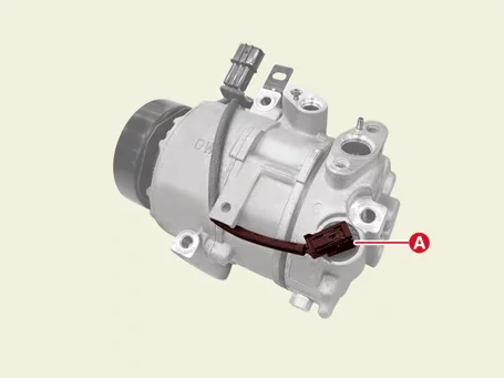
- Disconnect the ECV connector (A).
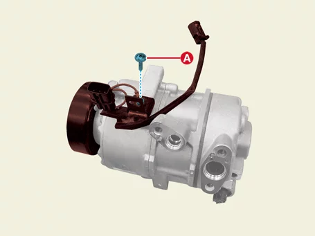
- Remove the stator grounding screw (A).
- Remove the stator assembly (B) after removing the snap ring (A) by using the snap ring pliers.
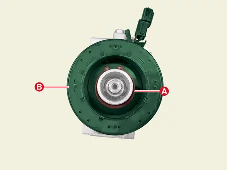
Reassembly
- Reassemble in the reverse order of disassembly.
- Wipe the moving surfaces of the pulley and compressor with a volatile solvent.
- Make sure that the snap ring is fully seated in the groove after assembling the snap ring.
- Make sure that the pulley rotates smoothly after assembling the pulley.
- Removed snap rings must be replaced with new ones.
Condenser Removal and Installation
Removal
Condenser[G 1.6 T-GDI GAMMA II]- Recover the refrigerant with Recovery/Recycling/Charging equipment. (Refer to Air conditioning System - "Refrigerant Recovery/Recycling/Charging/Vacuum/Leak Test")
- Remove the front bumper assembly. (Refer to Body - "Front Bumper Assembly")
- Remove the air guard (A) after removing the bolts.

- Remove the oil cooler (A) after removing the bolts.
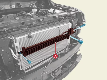
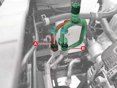
- Remove the suction & liquid hose (A) and discharge hose (B) after removing the nuts.
Tightening torque : 19.6 - 24 N·m
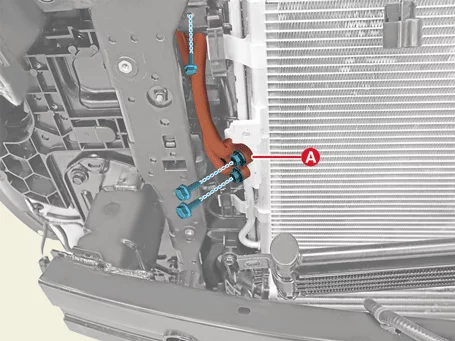
- Remove the condenser pipe (A) after removing the bolts.
Tightening torque : 8.8 - 13,7 N·m
- Remove the condenser (A).
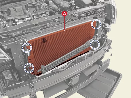
 |
- Recover the refrigerant with Recovery/Recycling/Charging equipment. (Refer to Air conditioning System - "Refrigerant Recovery/Recycling/Charging/Vacuum/Leak Test")
- Remove the front bumper assembly. (Refer to Body - "Front Bumper Assembly")
- Remove the air guard (A) after removing the bolts.
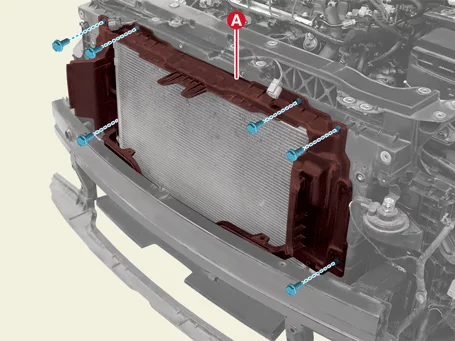
- Remove the suction & liquid hose (A) and discharge hose (B) after removing the nuts.
Tightening torque : 19.6 - 24 N·m

- Remove the condenser (A).
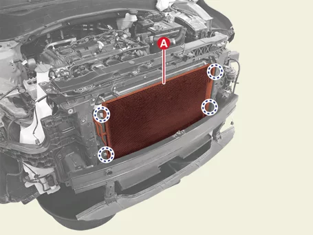
|
Installation
- Install in reverse order of removal.
- Perform refrigerant leak Test / vacuum / charging. (Refer to Air conditioning System - "Refrigerant Recovery/Recycling/Charging/Vacuum/Leak Test")
- Perform the compressor oil inspection. (Refer to Air conditioning System - "Compressor Oil")
Receiver-Drier Removal and Installation
Removal
- Remove the condenser. (Refer to Air conditioning System - "Condenser")
- Remove the cap (A) on the lower part of the condenser by using the L wrench.
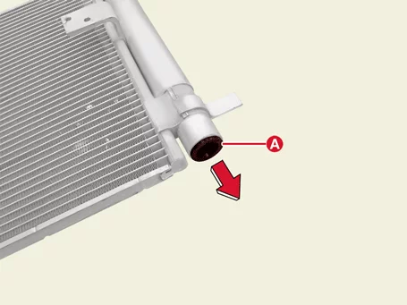
- Remove the receiver drier filter (A) and O-ring (B).

- Remove the desiccant (A) in the receiver drier.
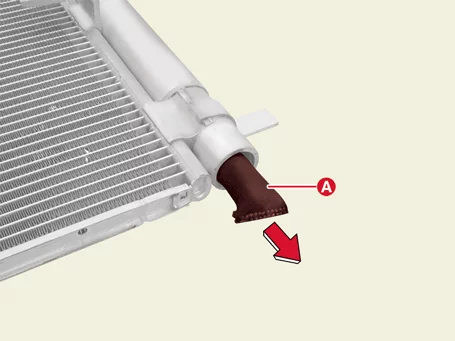
Installation
- Install in reverse order of removal.
- Perform refrigerant leak Test / vacuum / charging. (Refer to Air conditioning System - "Refrigerant Recovery/Recycling/Charging/Vacuum/Leak Test")
- Perform the compressor oil inspection. (Refer to Air conditioning System - "Compressor Oil")
A/C Pressure Transducer Description and Operation
Description
The air conditioner pressure transducer measures the pressure in the high-pressure line and converts it into a voltage value. When the converted output value is sent to the engine ECU, the engine ECU operates the cooling fan at high and low speeds to prevent pressure rise, and if the refrigerant pressure is too high or too low, the compressor stops working to optimize and protect the air conditioning system.A/C Pressure Transducer Removal and Installation
Removal
[G 1.6 T-GDI GAMMA II]- Disconnect the battery negative ( - ) terminal.
- Recover the refrigerant with Recovery/Recycling/Charging equipment. (Refer to Air conditioning System - "Refrigerant Recovery/Recycling/Charging/Vacuum/Leak Test")
- Disconnect the A/C pressure transducer connector (A).
- Remove the air conditioner pressure transducer (A).
Tightening torque : 9.8 - 11,8 N·m
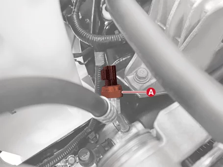
- Disconnect the battery negative ( - ) terminal.
- Recover the refrigerant with Recovery/Recycling/Charging equipment. (Refer to Air conditioning System - "Refrigerant Recovery/Recycling/Charging/Vacuum/Leak Test")
- Disconnect the A/C pressure transducer connector (A).
- Remove the air conditioner pressure transducer (A).
Tightening torque : 9.8 - 11,8 N·m

Installation
- Install in reverse order of removal.
- Perform refrigerant leak Test / vacuum / charging. (Refer to Air conditioning System - "Refrigerant Recovery/Recycling/Charging/Vacuum/Leak Test")
Evaporator Temperature Sensor Description and Operation
Description
The evaporator temperature sensor is installed on the evaporator to prevent freezing by sensing the temperature of the evaporator core. A NTC thermistor is installed inside the sensor, so when the temperature decreases, the resistance value increases, and when the temperature increases, the resistance value decreases.Evaporator Temperature Sensor Removal and Installation
Removal
- Remove the evaporator core. (Refer to Heating, Ventilation And Air Conditioning - "Evaporator Core")
- Remove the evaporator temperature sensor (A).

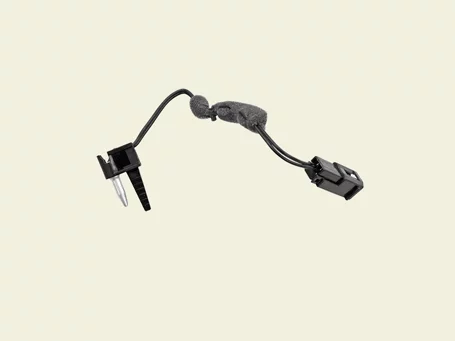
Installation
- Install in reverse order of removal.
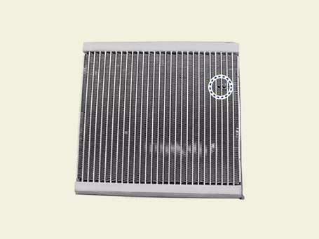 |
Evaporator Temperature Sensor Inspection
Inspection
- Turn the IG "ON".
- Turn on the air conditioner switch.
- Measure the resistance of the ( + ) and ( - ) terminals after connecting the multimeter to the evaporator temperature sensor.
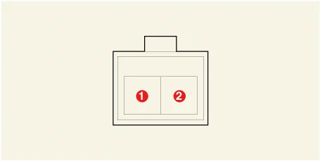
1. Evaporator Sensor ( + ) 2. Sensor Ground
Temperature (°C (°F) Resistance (kΩ) Voltage (V) -10 (14) 17.93 3.21 0 (32) 11.36 2.66 10 (50) 7.40 2.13 20 (68) 4.94 1.65 30 (86) 3.369 1.26 40 (104) 2.348 0.95
Photo Sensor Description and Operation
Description
The photo sensor (daylight sensor) is located above the sensor speaker grille. It has a built-in photovoltaic diode (sensing solar radiation). Luminescence appears in the part where light is received, and electric force is generated in proportion to the amount of light emission, and this electric force is transmitted to the automatic temperature control module to compensate for air volume and discharge temperature.Photo Sensor Removal and Installation
Removal
- Remove the photo sensor. (Refer to Body Electrical System - "Auto Light Sensor")
Installation
- Install in reverse order of removal.
Ambient Temperature Sensor Description and Operation
Description
- It is installed on the front of the condenser and senses the temperature of the outside air. It is a NTC thermistor type in which the resistance value decreases when the temperature rises and the resistance value increases when the temperature decreases.
- It is used for discharge temperature control, sensor compensation, temperature control door control, blower motor speed control, mix mode control, and in-vehicle humidity control.
Ambient Temperature Sensor Removal and Installation
Removal
- Remove the front bumper assembly. (Refer to Body - "Front Bumper Assembly")
- Disconnect the ambient temperature sensor connector (A).
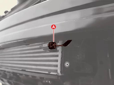
- Remove the ambient temperature sensor (A).

Installation
- Install in reverse order of removal.
Ambient Temperature Sensor Inspection
Inspection
- Check whether the resistance values of terminals 1 and 2 change by applying the temperature change of the air to the outside temperature sensor.
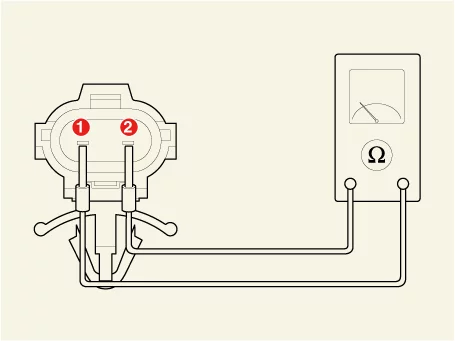
1. Ambient Temperature ( + ) 2. Sensor Ground
Sensor resistanceTemperature [°C (°F)] Resistance (kΩ) -40 (-40) 927.5 -30 (-22) 507.0 -20 (-4) 284.5 -10 (10) 164.2 0 (32) 97.5 10 (50) 59.6 20 (68) 37.46 30 (86) 24.18 40 (104) 16.00 50 (122) 10.83 60 (140) 7.48 70 (158) 5.26 80 (176) 3.77
Auto Defogging Sensor Description and Operation
Description
The auto defogging sensor is installed on the vehicle's windshield to detect moisture and removes it early before fogging occurs, and improves visibility and comfort.Auto Defogging Sensor Removal and Installation
Removal
- Disconnect the battery negative ( - ) terminal.
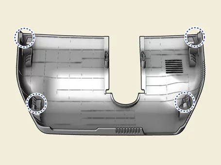
- Remove the multi sensor blanking cover (A).

- Remove the multi sensor cover (A) in the direction of the arrow.
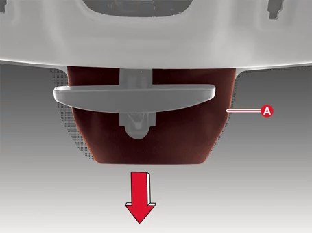
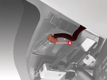
- Disconnect the auto defogging sensor connector (A).
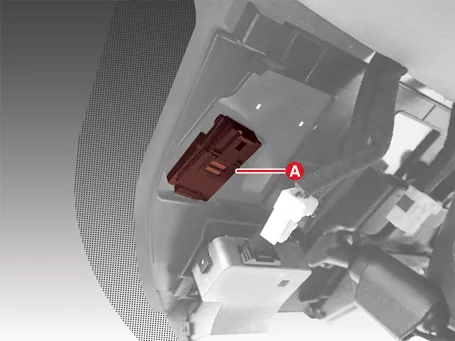
- Remove the auto defogging sensor (A).
Installation
- Install in reverse order of removal.
Was this page helpful?