Heating,Ventilation And Air Conditioning
Components and Components Location
In this manual: Heating,Ventilation And Air Conditioning
36steps
~216min
4/5difficulty
Done 0 of 36
Contents:
Components and Components Location
Component
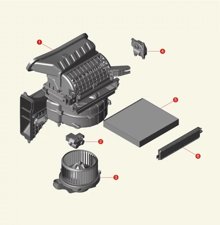
| 1. Blower Unit 2. PWM-FET 3. Blower Motor |
4. Intake Actuator 5. Climate Control Air Filter 6. Climate Control Air Filter Cover |
On Vehicle Inspection
On Vehicle Inspection
Diagnosis with KDS
- The heating,ventilation and air conditioning system can be more quickly diagnosed for problems with the KDS (Refer to "DTC guide").
- Self diagnosis : Inspect the Diagnostic Trouble Code (DTC) with the KDS. (Refer to DTC guide when fault code is found.)
Refer to the KDS screen for operating conditions and details.
Blower Unit Removal and Installation
Removal
- Separate the heater unit and blower unit. (Refer to Heater - "Heater Unit")
Installation
- Install in reverse order of removal.
Blower Motor Removal and Installation
Removal
- Disconnect the battery negative ( - ) terminal.
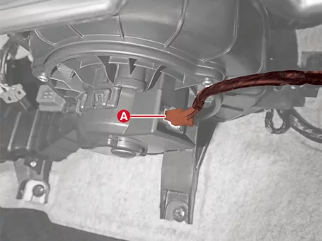
- Disconnect the blower motor connector (A).
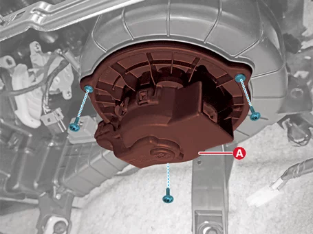
- Remove the blower motor (A) after removing the screws.
Installation
- Install in reverse order of removal.
Blower Motor Inspection
Inspection
- Turn IG OFF.
- Disconnect the blower motor connector.
- Apply voltage to the ( + ) terminal and ground the ( - ) terminal to check whether the motor is running.
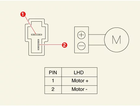
- If the blower motor does not work, replace it with a new blower motor.
Climate Control Air Filter Description and Operation
Description
The air filter for the air conditioner installed on the blower unit removes foreign substances or odors. The particle filter not only removes general dust but also serves as a odor-removing filter to maintain a comfortable indoor environment.Climate Control Air Filter Replacement
Replacement
|

- Open the glove box (A).
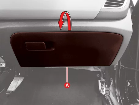
- Remove the air damper (A).
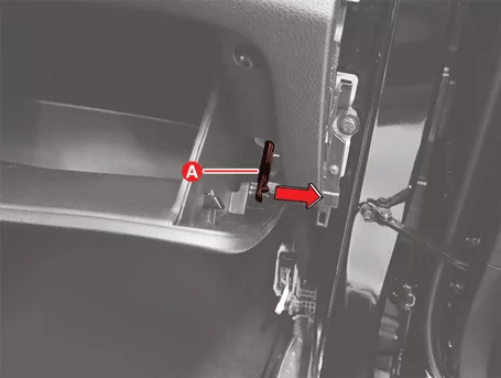
- Press the stopper of the glove box (A) in the direction of the arrow to lower it.

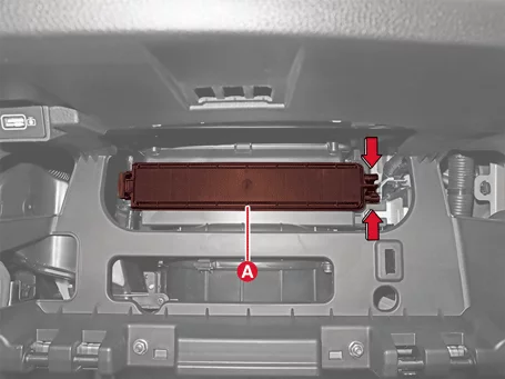
- Remove the air filter cover (A) for air conditioning by pressing the filter cover knob in the direction of the arrow.
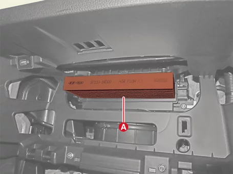
- Replace the air filter (A) for air conditioning.
- Install in reverse order of removal.
- Replace the air filter for air conditioning according to the replacement cycle of the instruction manual.
- When driving in an area with severe air pollution or in an area where a lot of fumes are generated due to poor road conditions, frequent inspection and replacement are required.
Intake Actuator Description and Operation
Description
- The intake actuator installed on the blower unit adjusts the intake door according to the signal from the control unit.
- Press the Fresh air mode/Recirculation mode switch to switch to the recirculation or fresh air intake mode.
Intake Actuator Removal and Installation
Removal
- Remove the Integrated Body Control Unit (IBU). (Refer to Body Electrical System - "Integrated Body Control Unit (IBU)")
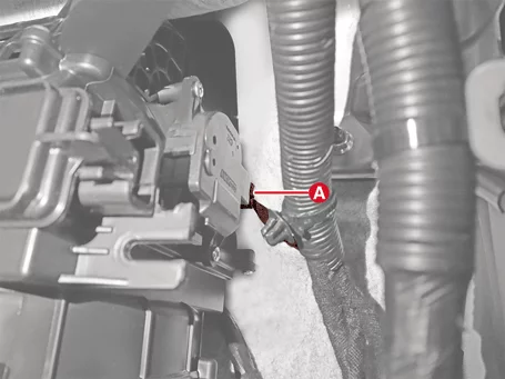
- Disconnect the intake actuator connector (A).
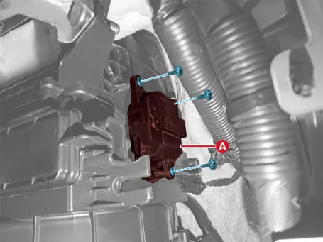
- Remove the intake actuator (A) after removing the screws.
Installation
- Install in reverse order of removal.
Intake Actuator Inspection
Inspection
- Turn the IG OFF.
- Disconnect the intake actuator connector.
- Connect the power ( + ) terminal to the intake actuator connector terminal 3 and the ( - ) terminal to the 4 terminal to check whether the actuator is driven in the outside air direction.

1. -
2. -
3. Recirculation
4. Fresh Air5. Sensor Power (+5 V)
6. Feedback Signal
7. Sensor Ground - Connect the intake actuator connector.
- Turn the IG ON.
- Measure the voltage across terminals 6 - 7.
Door Position Voltage (V) Error Detection (V) Fresh Air 0.5 ± 0.15 Low voltage : less than 0.1
High voltage : over 4.9Recirculation 4.5 ± 0.15 - If the measured voltage does not match with the specification, replace it with a new intake actuator.
Blower Resistor Description and Operation
Description
The fan speed is adjusted by precisely controlling the voltage applied to the blower motor.Blower Resistor Removal and Installation
Removal
- Remove the crash pad center panel. (Refer to Body - "Crash Pad Lower Panel")
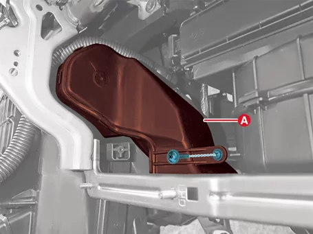
- Remove the passenger's side shower duct (A) after removing the screw.
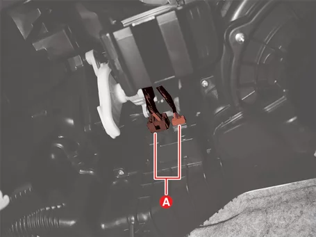
- Disconnect the blower resistor connectors (A).
- Remove the blower resistor (A) after removing the screws.
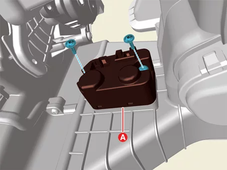
Installation
- Install in reverse order of removal.
Blower Resistor Inspection
- Measure the resistance between the terminals.
- If measured resistance is not within specification, the blower resistor must be replaced.
- Terminal
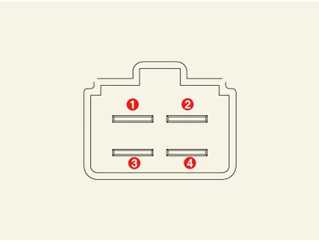
1. Middle low
2. Middle high3. Low
4. High - Circuit Diagram

Item Number Resistor (Ω) / Temperture (°C) Resistance value 1 1.4 2 1.0 3 0.5 Fuse temperture 4 200 - 220
- Terminal
PWM-FET Description and Operation
Description
The blower fan speed is adjusted by precisely controlling the voltage applied to the blower motor.PWM-FET Removal and Installation
Removal
- Remove the crash pad center panel. (Refer to Body - "Crash Pad Lower Panel")
- Remove the passenger's side shower duct (A) after removing the screw.
- Disconnect the blower resistor connector (A).
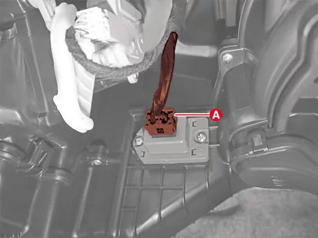
- Remove the blower resistor (A) after removing the screws.
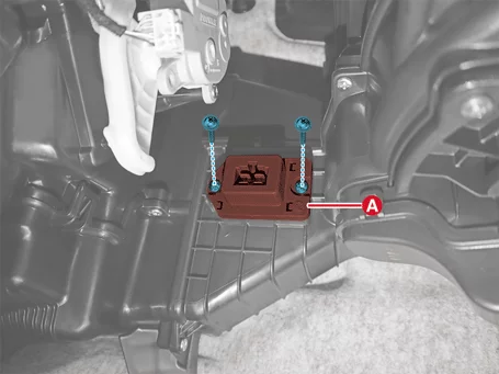
Installation
- Install in reverse order of removal.
PWM-FET Inspection
Inspection
- Turn the IG ON.
- The air conditioner controls the speed of the blower motor by controlling the gate terminal of the PWM-FET.
- Measure the voltage between the terminals of the blower motor by manually operating the control switch.
- Terminal
Terminal Blower level Voltage (V) 2 - 4 1 speed 3.8 - 4.8 8 speed 11 - 14 - Circuit Diagram

- Terminal
Was this page helpful?