Heater & A/C Control Unit (Manual) Connector and Terminal Information
In this manual: Heating,Ventilation And Air Conditioning
13steps
~78min
3/5difficulty
Done 0 of 13
Contents:
Heater & A/C Control Unit (Manual) Connector and Terminal Information
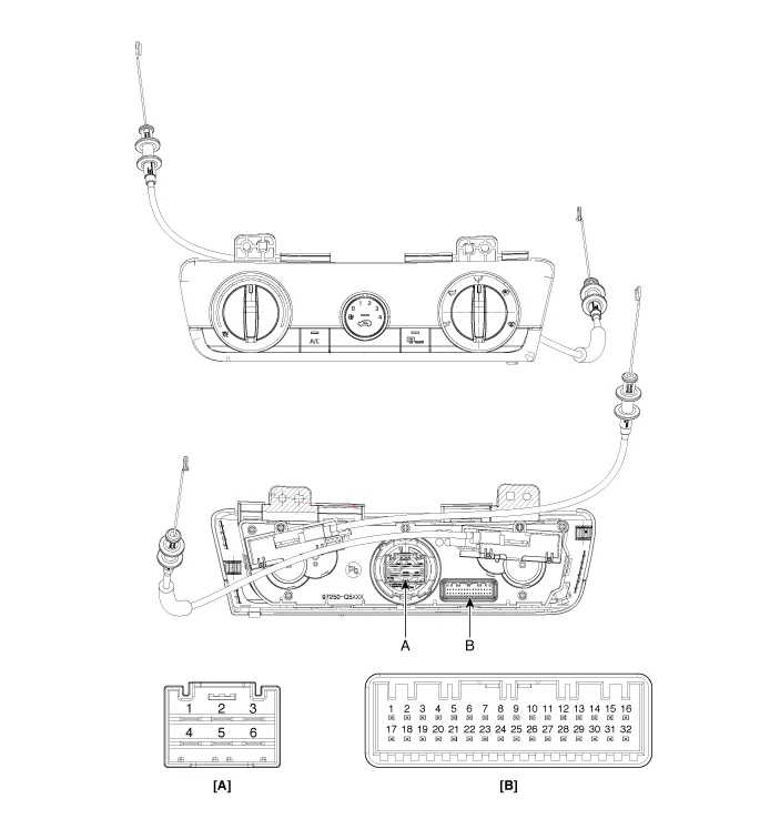
Connector And Terminal Function
Pin NO
Connector A
Pin NO
Connector A
1
Battery ( + )
17
IG 2
2
ISG Battery ( + )
18
IG 1
3
ILL ( + )
19
-
4
Sensor REF (+5 V)
20
Max blower on signal
5
-
21
PTC Relay 3
6
-
22
PTC Relay 2
7
Intake actuator feedback
23
PTC on signal
8
Evaporator temperature sensor ( + )
24
-
9
Ambient temperature sensor ( + )
25
P-CAN (High)
10
Mode actuator (Vent)
26
P-CAN (Low)
11
Mode actuator (Def)
27
-
12
Heateds IND (Front)
28
ECV ( + )
13
HTD (Rear defroster indicator lamp)
29
ECV ( - )
14
Detent out ( - )
30
-
15
Blower on signal to common
31
Sensor ground
16
ILL ( - )
32
Ground
Heater & A/C Control Unit (Manual) Removal and Installation
Removal
Disconnect the negative ( - ) battery terminal.
Remove the glove box. (Refer to Body - "Glove Box")
Remove the crash pad lower panel. (Refer to Body - "Crash Pad Panel")
Remove the passenger's side crash pad garnish. (Refer to Body - "Crash Pad Garnish")
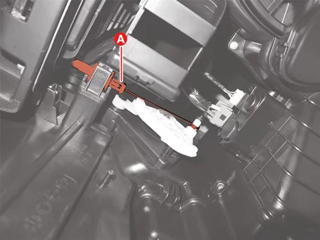
Remove the driver's side shower duct (A) after removing the screw.
Disconnect the heater & A/C control unit cable (A). [Driver's Side] [Passenger's Side]
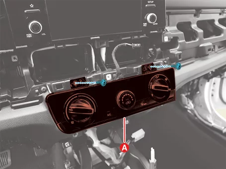
Remove the heater & A/C control unit (A) after removing the screws.
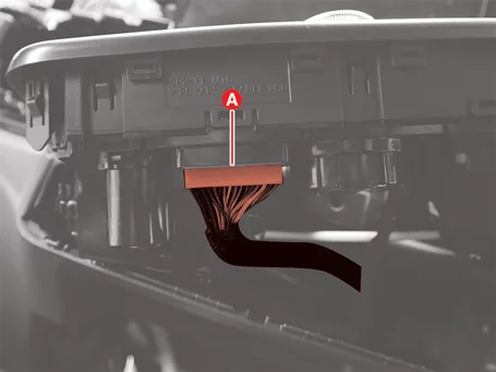
Disconnect the heater & A/C control unit connectors (A).
Installation
Install in reverse order of removal.
Heater & A/C Control Unit (Auto) On Vehicle Inspection
On Vehicle Inspection
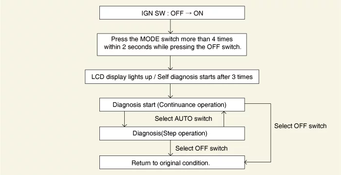
Self Diagnosis
During the self-diagnosis, fault code is displayed on the set temperature display and turn off all the others.
During the self-diagnosis, the air conditioning control remains OFF.
During the self-diagnosis, the following fault details (self-diagnosis code) are displayed on the set temperature display unit by blinking at 0.5 second intervals.
When IG OFF & ON during self-diagnosis, the system returns to the OFF state.
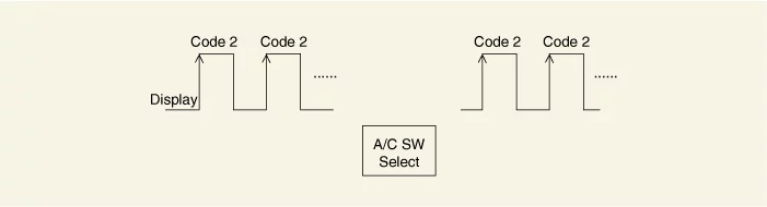
How to display fault codes
Continuous operation : Normal or in case of one fault
Continuous operation : Multiple faults
During STEP operation
a.
Normal or one fault is same as continuous operation.
b.
In case of multiple faults
For troubleshooting procedures, refer to the DTC code.
Heater & A/C Control Unit (Auto) Connector And Terminal Function
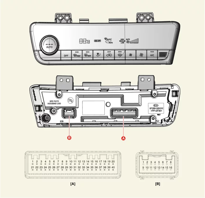
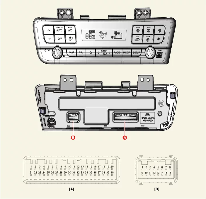
Connector And Terminal Function
[Display Audio Type]
Pin No
Connector A
Connector B
1
Battery ( + )
-
2
ISG Battery ( + )
-
3
ILL ( + ) (TAIL)
-
4
Sensor ground REF (+5 V)
Defogging actuator (Feedback)
5
Mode control actuator (Feedback)
Defogging actuator (Open)
6
Temperature actuator (Feedback)
Defogging actuator (Close)
7
Intake actuator (Feedback)
-
8
Evaporator temperature sensor ( + )
Rear glass defogger indicator
9
Ambient temperature senor ( + )
Rear glass defogger switch
10
Mode control actuator (Vent)
-
11
Mode control actuator (Def)
-
12
Temperature actuator (Cool)
Defog (TEMP)
13
Temperature actuator (Warm)
Defog (SCK)
14
Intake actuator (Fresh)
Defog (DATA)
15
Intake actuator (Recirculation)
-
16
HTD (Rear defog indicator)
Ground
17
Rear defogging switch
18
Blower relay
19
-
20
Rheostat ILL ( + )
21
IG 2
22
IG 1
23
Blower motor ( + )
24
Photo sensor ( - )
25
-
26
-
27
-
28
-
29
-
30
-
31
Detent out ( - )
32
-
33
P-CAN (HIGH)
34
P-CAN (LOW)
35
FET (Drain Feedback)
36
FET (Gate)
37
ECV ( + )
38
ECV ( - )
39
Sensor ground ( - )
40
Ground ( - )
[AVNT Type]
Pin No
Connector A
Connector B
1
Battery ( + )
-
2
ISG Battery ( + )
-
3
ILL ( + ) (TAIL)
-
4
Sensor ground REF (+5 V)
Defogging actuator (Feedback)
5
Mode control actuator (Feedback)
Defogging actuator (Open)
6
Temperature actuator (Feedback)
Defogging actuator (Close)
7
Intake actuator (Feedback)
-
8
Evaporator temperature sensor ( + )
Rear glass defogger indicator
9
Ambient temperature senor ( + )
Rear glass defogger switch
10
Mode control actuator (Vent)
-
11
Mode control actuator (Def)
-
12
Temperature actuator (Cool)
Defog (TEMP)
13
Temperature actuator (Warm)
Defog (SCK)
14
Intake actuator (Fresh)
Defog (DATA)
15
Intake actuator (Recirculation)
-
16
HTD (Rear defog indicator)
Ground
17
Rear defogging switch
18
Blower relay
19
-
20
Rheostat ILL ( + )
21
IG 2
22
IG 1
23
Blower motor ( + )
24
Photo sensor ( - )
25
-
26
-
27
-
28
-
29
-
30
AVNT head unit keyboard reset
31
Detent out ( - )
32
-
33
P-CAN (HIGH)
34
P-CAN (LOW)
35
FET (Drain Feedback)
36
FET (Gate)
37
ECV ( + )
38
ECV ( - )
39
Sensor ground ( - )
40
Ground ( - )
Heater & A/C Control Unit (Auto) Removal and Installation
Removal
Remove the center air vent. (Refer to Body - "Crash Pad Air Vent")
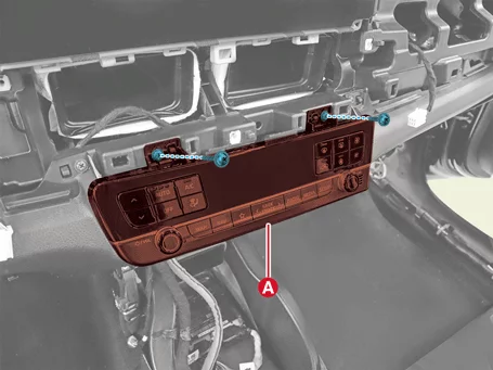
Remove the heater and air conditioner control unit (A) after removing the screws.
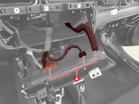
Disconnect the heater and air conditioner control unit hose and connectors (A).