Emission Control System

Evaporative Emission Control System

49steps
~294min
4/5difficulty
010203040505.94N·mlb·ft
Tightening torque found on this page
Done 0 of 49

Contents:

Description and Operation

Description

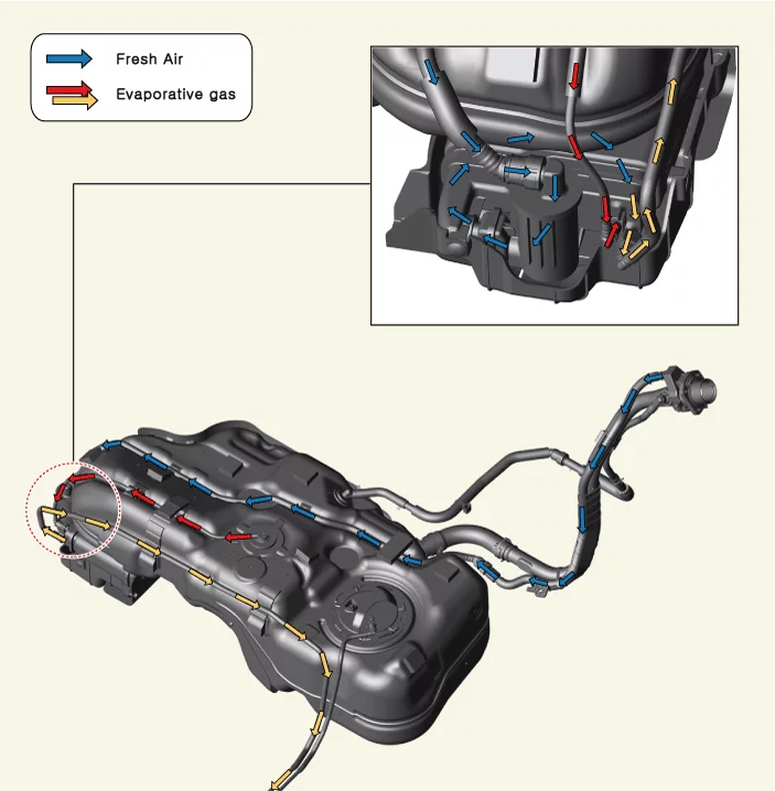
  • Evaporative emission control system is the system that recirculates and burns evaporative gases in the fuel tank to reduce hydrocarbons.
  • The evaporative emission control system comprises a canister to neutralize the evaporative emissions using activated carbon, and a purge control solenoid valve to circulate the evaporative emissions to the intake manifold.

Operation

Emission Control System — Evaporative Emission Control System / Description and Operation / Operation illustration

Inspection

Inspection

[EVAP. Leakage Test]

  1. Perform the evaporative gas leakage test by using the KDS. (S/W Management → Engine Control → Evap. Leakage Test)
    Information
    • Test Condition
    1. Vehicle : Stop
    2. Fuel level : 15 - 85%
    3. No DTC
    4. Engine idle
    5. Engine warm-up [Coolant temperature 80 °C or higher]
    • Refer to the KDS screen for operating conditions and details.

Canister Components and Components Location

Component Location

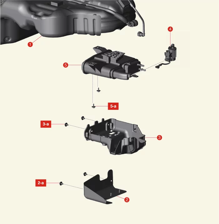
Emission Control System — Evaporative Emission Control System / Canister / Components and Components Location / Component Location illustration
1. Fuel Tank
2. Canister Protector
2-a. 3.9 - 5,9 N·m (0.4 - 0.6 kgf·m, 2.9 - 4.3 lb·ft, 34.7 - 52.1 lb·in)
3. Canister Heat Protector
3-a. 3.9 - 5,9 N·m (0.4 - 0.6 kgf·m, 2.9 - 4.3 lb·ft, 34.7 - 52.1 lb·in)
4. Canister Close Valve (CCV) & Fuel Tank Air Filter
5. Canister
5-a. 3.9 - 5,9 N·m (0.4 - 0.6 kgf·m, 2.9 - 4.3 lb·ft, 34.7 - 52.1 lb·in)

Canister Removal and Installation

Removal

  1. Disconnect the battery negative ( - ) terminal.
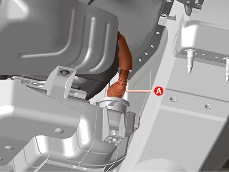
  2. Disconnect the Canister Close Valve (CCV) connector (A).
    Emission Control System — Evaporative Emission Control System / Canister / Removal and Installation / Removal illustration
  3. Separate the air ventilation hose (A).
    Emission Control System — Evaporative Emission Control System / Canister / Removal and Installation / Removal illustration
    Note
    Be careful not to use excessive force since the vapor hoses are connected.
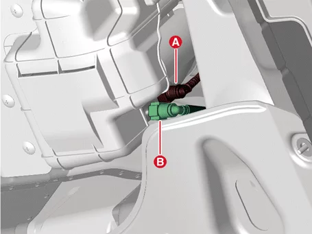
  4. Separate the vapor hose (A, B).
    Emission Control System — Evaporative Emission Control System / Canister / Removal and Installation / Removal illustration
  5. Remove the canister (A) after removing the bolts.
    Tightening torque : 3.9 - 5,9 N·m (0.4 - 0.6 kgf·m, 2.9 - 4.3 lb·ft, 34.7 - 52.1 lb·in)
    Emission Control System — Evaporative Emission Control System / Canister / Removal and Installation / Removal illustration
    Information
    Remove the canister (A) by pushing it in the direction of arrow.
    Emission Control System — Evaporative Emission Control System / Canister / Removal and Installation / Removal illustration
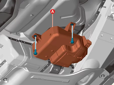
  6. Remove the canister heat protector (A).
    Tightening torque : 3.9 - 5,9 N·m (0.4 - 0.6 kgf·m, 2.9 - 4.3 lb·ft, 34.7 - 52.1 lb·in)
    Emission Control System — Evaporative Emission Control System / Canister / Removal and Installation / Removal illustration
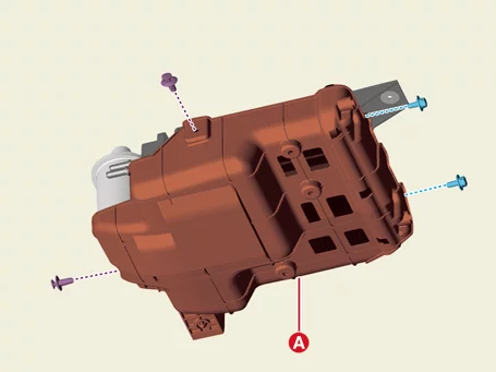
  7. Remove the canister cover (A).
    Tightening torque : 3.9 - 5,9 N·m (0.4 - 0.6 kgf·m, 2.9 - 4.3 lb·ft, 34.7 - 52.1 lb·in)
    Emission Control System — Evaporative Emission Control System / Canister / Removal and Installation / Removal illustration
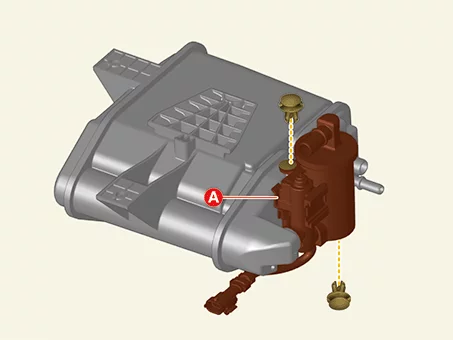
  8. Remove the fuel tank air filter and CCV (A).
    Emission Control System — Evaporative Emission Control System / Canister / Removal and Installation / Removal illustration

Installation

  1. Install in reverse order of removal.
    Note
    • Install the canister to the specified torque.
    • If the canister is dropped, it may cause internal damage. (Do not reuse)
    • Be careful not to get foreign matters into the canister.

Canister Inspection

Inspection

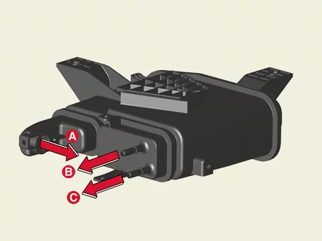
  1. Visually inspect the following items. - Crack or leakage of the canister - Loose connection, distortion, or damage of the vapor hose/tube
    Emission Control System — Evaporative Emission Control System / Canister / Inspection illustration
    A : Canister ↔ Atmosphere B : Canister ↔ Fuel tank C : Canister ↔ Intake manifold

Canister Close Valve (CCV) Specifications

Specification

Item Specification
Rated voltage (V) 12
Operating voltage (V) 10 - 16
Resistance (Ω) 19.8 - 21.8 [20 °C]
Operating pressure [kPa (kgf/cm2 , psi)] -2.5 (-0.02, -0.36)

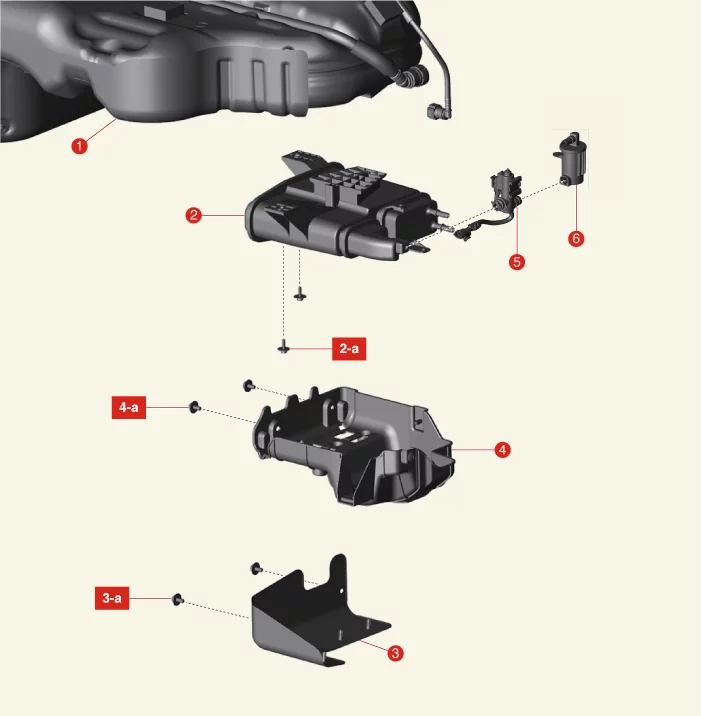
Canister Close Valve (CCV) Components and Components Location

Component Location

Emission Control System — Evaporative Emission Control System / Canister Close Valve (CCV) / Components and Components Location / Component Location illustration
1. Fuel Tank
2. Canister
2-a. 3.9 - 5,9 N·m (0.4 - 0.6 kgf·m, 2.9 - 4.3 lb·ft, 34.7 - 52.1 lb·in)
3. Canister Protector
3-a. 3.9 - 5,9 N·m (0.4 - 0.6 kgf·m, 2.9 - 4.3 lb·ft, 34.7 - 52.1 lb·in)
4. Canister Heat Protector
4-a. 3.9 - 5,9 N·m (0.4 - 0.6 kgf·m, 2.9 - 4.3 lb·ft, 34.7 - 52.1 lb·in)
5. Canister Close Valve (CCV)
6. Fuel Tank Air Filter

Canister Close Valve (CCV) Description and Operation

Description

Canister Close Valve (CCV) is installed on the canister ventilation line. It seals evaporative emission control system by shutting the canister from the atmosphere when leak detecting system operates.
Emission Control System — Evaporative Emission Control System / Canister Close Valve (CCV) / Description and Operation / Description illustration

Canister Close Valve (CCV) On Vehicle Inspection

On Vehicle Inspection

Diagnosis with KDS
  1. The evaporative emission control system can be more quickly diagnosed for problems with the KDS (Refer to "DTC guide").
    1. Self Diagnosis : Inspect the Diagnostic Trouble Code (DTC) with the KDS (Refer to DTC guide when fault code is found)
    2. Data Analysis : Checking the system input/output data state (Data Analysis → System Selection → Engine)
    3. Actuation test : Checking the system operation condition (Data Analysis → System Selection → Engine → Actuation test → Canister Shut Off Valve (OBD-2 Only) / Canister Shut Off Valve Clocked (OBD-2 Only))
    Information
    Refer to the KDS screen for operating conditions and details.
  2. Turn the ignition switch OFF.
  3. Disconnect the Canister Close Valve (CCV) connector (A).
    Emission Control System — Evaporative Emission Control System / Canister Close Valve (CCV) / On Vehicle Inspection illustration
  4. Measure resistance between the CCV terminal 1 and 2.
  5. Check that the resistance is within the specification.
    Item Specification
    Resistance (Ω) 19.8 - 21.8 [20 °C]
  6. Separate the air ventilation hose (A).
    Emission Control System — Evaporative Emission Control System / Canister Close Valve (CCV) / On Vehicle Inspection illustration
  7. Connect a vacuum pump to the nipple.
  8. Ground the CCV control line and apply battery voltage to the CCV power supply line.
  9. Apply vacuum and check the valve operation.
    Item Specification
    Operating voltage (V) 10 - 16
    Operating pressure [kPa (kgf/cm2 , psi)] -2.5 (-0.02, -0.36)
Component Inspection [Resistance Measurement] [Air Tightness Test]

Canister Close Valve (CCV) Removal and Installation

Removal

  1. Disconnect the battery negative ( - ) terminal.
  2. Disconnect the Canister Close Valve (CCV) connector (A).
    Emission Control System — Evaporative Emission Control System / Canister Close Valve (CCV) / Removal and Installation / Removal illustration
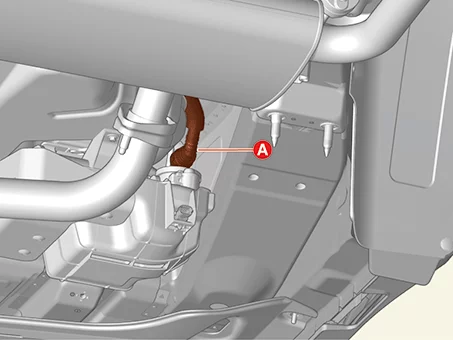
  3. Separate the air ventilation hose (A).
    Emission Control System — Evaporative Emission Control System / Canister Close Valve (CCV) / Removal and Installation / Removal illustration
    Note
    Be careful not to use excessive force since the vapor hoses are connected.
  4. Separate the vapor hose (A, B).
    Emission Control System — Evaporative Emission Control System / Canister Close Valve (CCV) / Removal and Installation / Removal illustration
  5. Remove the canister (A) after removing the bolts.
    Tightening torque : 3.9 - 5,9 N·m (0.4 - 0.6 kgf·m, 2.9 - 4.3 lb·ft, 34.7 - 52.1 lb·in)
    Emission Control System — Evaporative Emission Control System / Canister Close Valve (CCV) / Removal and Installation / Removal illustration
    Information
    Remove the canister (A) by pushing it in the direction of arrow.
    Emission Control System — Evaporative Emission Control System / Canister Close Valve (CCV) / Removal and Installation / Removal illustration
  6. Remove the canister heat protector (A).
    Tightening torque : 3.9 - 5,9 N·m (0.4 - 0.6 kgf·m, 2.9 - 4.3 lb·ft, 34.7 - 52.1 lb·in)
    Emission Control System — Evaporative Emission Control System / Canister Close Valve (CCV) / Removal and Installation / Removal illustration
  7. Remove the canister cover (A).
    Tightening torque : 3.9 - 5,9 N·m (0.4 - 0.6 kgf·m, 2.9 - 4.3 lb·ft, 34.7 - 52.1 lb·in)
    Emission Control System — Evaporative Emission Control System / Canister Close Valve (CCV) / Removal and Installation / Removal illustration
  8. Remove the fuel tank air filter and CCV (A).
    Emission Control System — Evaporative Emission Control System / Canister Close Valve (CCV) / Removal and Installation / Removal illustration
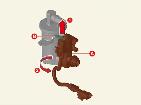
  9. Remove the CCV (A) by rotating CCV about 30 degrees in the direction of the arrow while lifting the holder (B).
    Emission Control System — Evaporative Emission Control System / Canister Close Valve (CCV) / Removal and Installation / Removal illustration

Installation

  1. Install in the reverse order of removal.
    Note
    • If the Canister Close Valve (CCV) is dropped, it may cause internal damage. (Do not reuse)
    • Be careful not to get contaminant into the CCV.

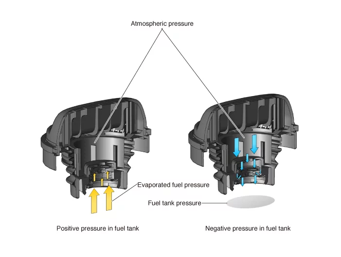
Fuel Filler Cap Description and Operation

Description

  • The fuel filler cap works as a check valve, allowing fluid to flow in only one direction.
  • It releases the vacuum getting the external air when the vacuum occurs inside the fuel tank and prevents vapor gas in the fuel tank from going into the atmosphere.
Emission Control System — Evaporative Emission Control System / Fuel Filler Cap / Description and Operation / Description illustration

Fuel Tank Air Filter Components and Components Location

Component Location

Emission Control System — Evaporative Emission Control System / Fuel Tank Air Filter / Components and Components Location / Component Location illustration
1. Fuel Tank
2. Canister
2-a. 3.9 - 5,9 N·m (0.4 - 0.6 kgf·m, 2.9 - 4.3 lb·ft, 34.7 - 52.1 lb·in)
3. Canister Protector
3-a. 3.9 - 5,9 N·m (0.4 - 0.6 kgf·m, 2.9 - 4.3 lb·ft, 34.7 - 52.1 lb·in)
4. Canister Heat Protector
4-a. 3.9 - 5,9 N·m (0.4 - 0.6 kgf·m, 2.9 - 4.3 lb·ft, 34.7 - 52.1 lb·in)
5. Canister Close Valve (CCV)
6. Fuel Tank Air Filter

Fuel Tank Air Filter Removal and Installation

Removal

  1. Disconnect the battery negative ( - ) terminal.
  2. Disconnect the Canister Close Valve (CCV) connector (A).
    Emission Control System — Evaporative Emission Control System / Fuel Tank Air Filter / Removal and Installation / Removal illustration
  3. Separate the air ventilation hose (A).
    Emission Control System — Evaporative Emission Control System / Fuel Tank Air Filter / Removal and Installation / Removal illustration
    Note
    Be careful not to use excessive force since the vapor hoses are connected.
  4. Separate the vapor hose (A, B).
    Emission Control System — Evaporative Emission Control System / Fuel Tank Air Filter / Removal and Installation / Removal illustration
  5. Remove the canister (A) after removing the bolts.
    Tightening torque : 3.9 - 5,9 N·m (0.4 - 0.6 kgf·m, 2.9 - 4.3 lb·ft, 34.7 - 52.1 lb·in)
    Emission Control System — Evaporative Emission Control System / Fuel Tank Air Filter / Removal and Installation / Removal illustration
    Information
    Remove the canister (A) by pushing it in the direction of arrow.
    Emission Control System — Evaporative Emission Control System / Fuel Tank Air Filter / Removal and Installation / Removal illustration
  6. Remove the canister heat protector (A).
    Tightening torque : 3.9 - 5,9 N·m (0.4 - 0.6 kgf·m, 2.9 - 4.3 lb·ft, 34.7 - 52.1 lb·in)
    Emission Control System — Evaporative Emission Control System / Fuel Tank Air Filter / Removal and Installation / Removal illustration
  7. Remove the canister cover (A).
    Tightening torque : 3.9 - 5,9 N·m (0.4 - 0.6 kgf·m, 2.9 - 4.3 lb·ft, 34.7 - 52.1 lb·in)
    Emission Control System — Evaporative Emission Control System / Fuel Tank Air Filter / Removal and Installation / Removal illustration
  8. Remove the fuel tank air filter and CCV (A).
    Emission Control System — Evaporative Emission Control System / Fuel Tank Air Filter / Removal and Installation / Removal illustration
  9. Remove the CCV (A) by rotating CCV about 30 degrees in the direction of the arrow while lifting the holder (B).
    Emission Control System — Evaporative Emission Control System / Fuel Tank Air Filter / Removal and Installation / Removal illustration

Installation

  1. Install in reverse order of removal.
    Note
    • Install the fuel tank air filter to the specified torque.
    • If fuel tank air filter is dropped, it may cause internal damage. (Do not reuse)
    • Be careful not to get foreign matters into the fuel tank air filter.

Fuel Tank Pressure Sensor (FTPS) Specifications

Specification

Item Specification
Rated voltage (V) 5
Operating voltage (V) 4.75 - 5.25
Operating temperature [°C (°F)] -30 to 100 (-22 to 212)
Operating pressure (kPa) -6.67 to 6.67

Item Specification
Pressure kPa -6.67 0 6.67
kgf/cm² -0.06 0 0.06
psi -0.96 0 0.96
Output voltage (V) 0.5 2.5 4.5

Fuel Tank Pressure Sensor (FTPS) Components and Components Location

Component Location

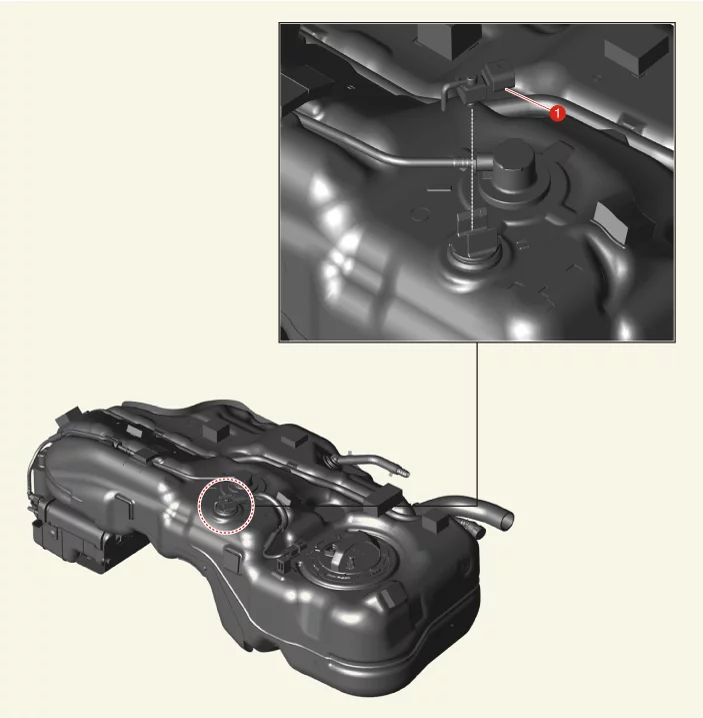
Emission Control System — Evaporative Emission Control System / Fuel Tank Pressure Sensor (FTPS) / Components and Components Location / Component Location illustration
1. Fuel Tank Pressure Sensor (FTPS)

Fuel Tank Pressure Sensor (FTPS) Description and Operation

Description

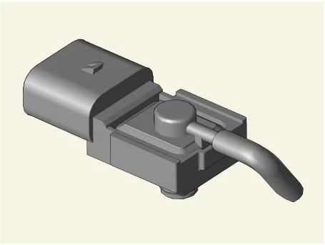
  • The Fuel Tank Pressure Sensor (FTPS) is a component of the evaporative emission control system and is installed on the fuel tank.
  • It checks the Purge Control Solenoid Valve (PCSV) operation and detects a leakage of the system.
Emission Control System — Evaporative Emission Control System / Fuel Tank Pressure Sensor (FTPS) / Description and Operation / Description illustration

Fuel Tank Pressure Sensor (FTPS) On Vehicle Inspection

On Vehicle Inspection

Diagnosis with KDS
  1. The evaporative emission control system can be more quickly diagnosed for problems with the KDS (Refer to "DTC guide").
    1. Self diagnosis : Inspect the Diagnostic Trouble Code (DTC) with the KDS (Refer to DTC guide when fault code is found)
    2. S/W Management : Controlling other features including system option setting and zero point adjustment (S/W Management → Engine Control → Evap. Leakage Test)
    Information
    Refer to the KDS screen for operating conditions and details.

Fuel Tank Pressure Sensor (FTPS) Removal and Installation

Removal

  1. Remove the fuel tank. (Refer to Engine Control / Fuel System - "Fuel Tank")
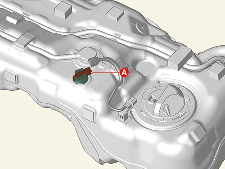
  2. Disconnect the Fuel Tank Pressure Sensor (FTPS) connector (A).
    Emission Control System — Evaporative Emission Control System / Fuel Tank Pressure Sensor (FTPS) / Removal and Installation / Removal illustration
  3. Remove the FTPS (A) from fuel tank.
    Emission Control System — Evaporative Emission Control System / Fuel Tank Pressure Sensor (FTPS) / Removal and Installation / Removal illustration

Installation

  1. Install in the reverse order of removal.
    Note
    • If the Fuel Tank Pressure Sensor (FTPS) is dropped, it may cause internal damage. (Do not reuse)
    • Be careful not to get foreign matters into the FTPS.

Purge Control Solenoid Valve (PCSV) Specification

Specification

Item Specification
Rated voltage (V) 13.4 - 13.6
Operating voltage (V) 9 - 16
Allowable transient voltage (V) 24 (1 min)
Minimum operating voltage (V) 9
Deactivation voltage (V) 1
Resistance (Ω) 18.5 - 22.5 [23 °C]

Purge Control Solenoid Valve (PCSV) Components and Components Location

Component Location

Emission Control System — Evaporative Emission Control System / Purge Control Solenoid Valve (PCSV) / Components and Components Location / Component Location illustration
1. Purge Control Solenoid Valve (PCSV)
1-a. 9.8 - 11,8 N·m

Purge Control Solenoid Valve (PCSV) Description and Operation

Description

  • Purge Control Solenoid Valve (PCSV) controls the passage between the canister and the intake manifold.
  • Fuel evaporative gas collected in the canister is supplied to the combustion chamber by the operation of the Purge Control Solenoid Valve (PSCV) under Engine Control Module (ECM) control.
Emission Control System — Evaporative Emission Control System / Purge Control Solenoid Valve (PCSV) / Description and Operation / Description illustration

Purge Control Solenoid Valve (PCSV) On Vehicle Inspection

On Vehicle Inspection

  1. Turn the IG OFF.
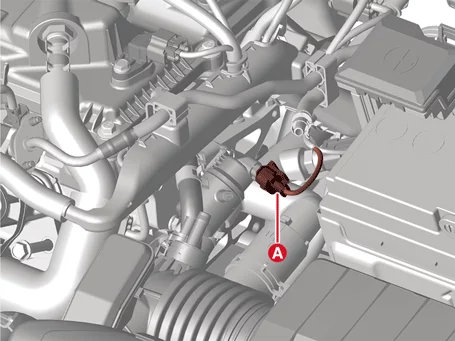
  2. Disconnect the Purge Control Solenoid Valve (PCSV) connector (A).
    Emission Control System — Evaporative Emission Control System / Purge Control Solenoid Valve (PCSV) / On Vehicle Inspection illustration
  3. Measure resistance between the PCSV terminals 1 and 2.
  4. Check that the resistance is within the specification.
    Item Specification
    Resistance (Ω) 18.5 - 22.5 [23 °C]

Purge Control Solenoid Valve (PCSV) Removal and Installation

Removal

  1. Disconnect the negative ( - ) terminal of the battery.
  2. Remove the engine cover. (Refer to Engine Mechanical System - "Engine Cover")
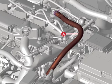
  3. Remove the breather hose (A).
    Emission Control System — Evaporative Emission Control System / Purge Control Solenoid Valve (PCSV) / Removal and Installation / Removal illustration
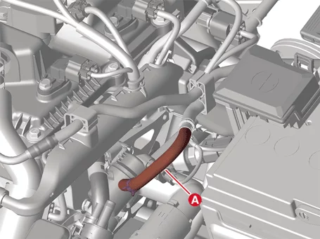
  4. Remove the vapor hose (A).
    Emission Control System — Evaporative Emission Control System / Purge Control Solenoid Valve (PCSV) / Removal and Installation / Removal illustration
  5. Disconnect the Purge Control Solenoid Valve (PCSV) connector (A).
    Emission Control System — Evaporative Emission Control System / Purge Control Solenoid Valve (PCSV) / Removal and Installation / Removal illustration
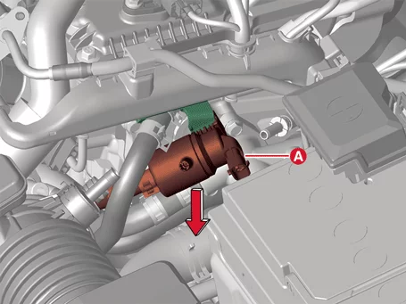
  6. Separate the PCSV (A) by pushing it in the direction of the arrow.
    Emission Control System — Evaporative Emission Control System / Purge Control Solenoid Valve (PCSV) / Removal and Installation / Removal illustration
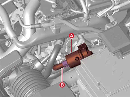
  7. Remove the PCSV (A) after removing the vapor hose (B).
    Emission Control System — Evaporative Emission Control System / Purge Control Solenoid Valve (PCSV) / Removal and Installation / Removal illustration

Installation

  1. Install in reverse order of removal.
    Note
    • If the Purge Control Solenoid Valve (PCSV) is dropped, it may cause internal damage. (Do not reuse)
    • Be careful not to get foreign matters into the PCSV.