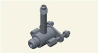
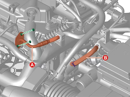
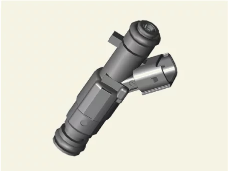
Used for connecting between the delivery pipe and the fuel feed line
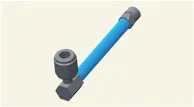
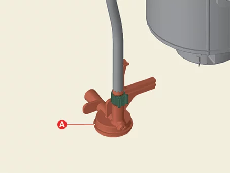
Fuel pressure gauge adapter 09353 - 24000
Used for connecting between the fuel pressure gauge adapter and the fuel pressure gauge
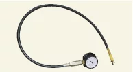
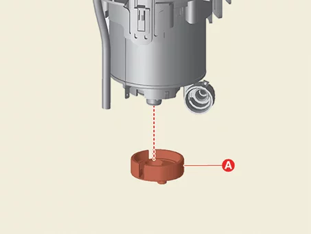
Fuel pressure gauge 09353 - 24100
Used for measuring the pressure in fuel line
Fuel Pressure Test
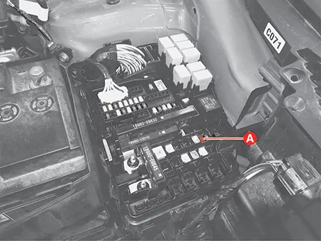
Release the residual pressure in fuel line. (Refer to Fuel Delivery System - "Release Residual Pressure in Fuel Line")
Remove the DTC surely with a KDS after the "Release Residual Pressure in Fuel Line" procedure since the DTC is occurred when removing the fuel pump relay.
Cover the connection with a clean cloth since the residual fuel may be released after "Release Residual Pressure in Fuel Line" procedures.
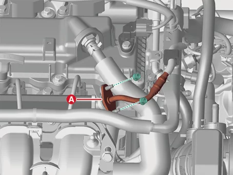
Install the Special Service Tool (SST).
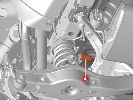
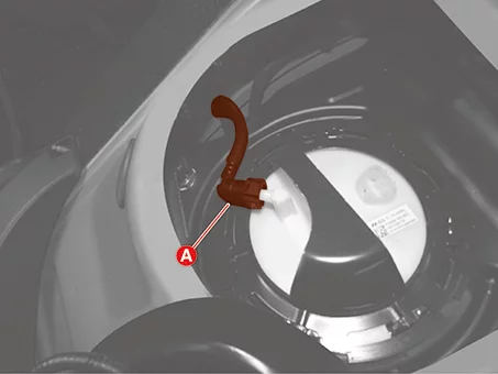
Separate the fuel feed tube (A).
Tightening torque : 8.8 - 11,8 N·m
Install the SST for measuring the fuel pressure to delivery pipe and fuel feed tube. (Refer to the figure below)
Check the leakage in the fuel line and SST installation area with IG ON.
Fuel pressure inspection
Measure the fuel pressure at idle state after starting the engine.
The fuel delivery system can be more quickly diagnosed for problems by using the KDS (Refer to "DTC guide").
Self diagnosis : Inspect the Diagnostic Trouble Code (DTC) using the KDS (Refer to DTC guide when fault code is found)
Data analysis : Checking the system input/output data state (Data Analysis → System Selection → Engine)
Actuation test : Checking the fuel pump operation condition (Data Analysis → System Selection → Engine → Actuation test → Fuel Pump Control(1st Stage))
Refer to the KDS screen for operating conditions and details
Component Inspection
Remove the rear seat cushion. (Refer to Body - "Rear Seat Assembly")
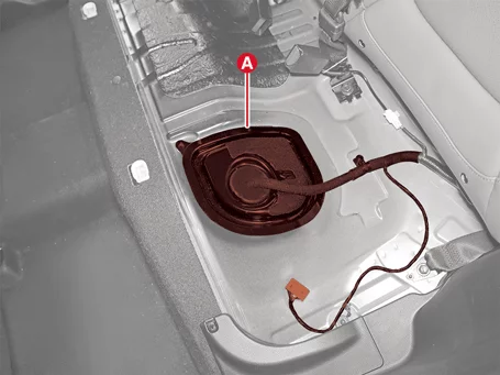
Remove the fuel pump service cover (A).
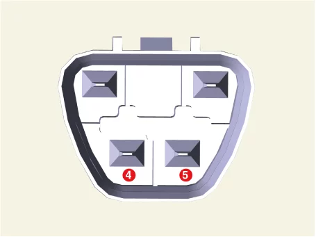
Disconnect the fuel pump module connector (A).
Check the fuel pump operation.
Terminal
Function
4
( + )
5
( - )
Fuel Pump Module Removal and Installation
Special Service Tool
Tool Name / Number
Illustration
Description
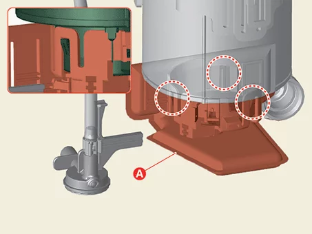
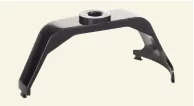
Low Fuel Pump Plate Cover Remover 09310 - B8100
Used for removing / installing the low pressure fuel pump plate cover
Removal
Cover the connection with a clean cloth since the residual fuel may be released after "Release Residual Pressure in Fuel Line" procedures.
Release the residual pressure in fuel line. (Refer to Fuel Delivery System - "Release Residual Pressure in Fuel Line")
Disconnect the battery negative ( - ) terminal.
Remove the rear seat cushion. (Refer to Body - "Rear Seat Assembly")
Remove the fuel pump service cover (A).
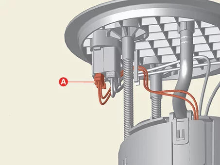
Disconnect the fuel pump module connector (A).
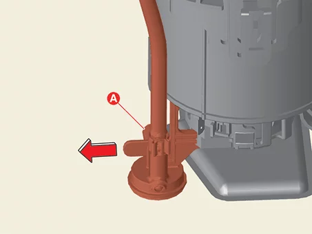
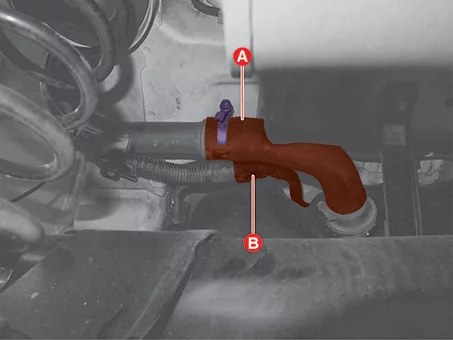
Separate the fuel feed tube (A).
Remove the plate cover by using the SST (09310 - B8100). Proper Use of SST and Safe Working Posture for Removing the Tightly Fastened Plate Cover (Play ▶)
Video: Proper Use of SST and Safe Working Posture for Removing the Tightly Fastened Plate Cover
Notes When Refering Video This video helps recognize potential hazards in advance and ensures procedures are performed correctly when safety precautions are required or when failure to follow steps or procedural errors could affect driving safety.
This video is created using common specifications and may differ from the actual vehicle.
The location and repair procedures of the parts may vary depending on vehicle model, model year, region, and specifications.
Check the KDS Guide for detailed information on how to use the KDS.
Check the manual for detailed maintenance procedures.
Unauthorized reproduction, distribution, or sharing of this video is prohibited.
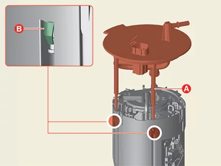
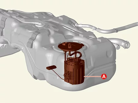
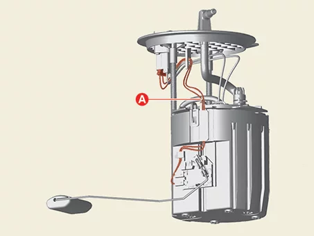
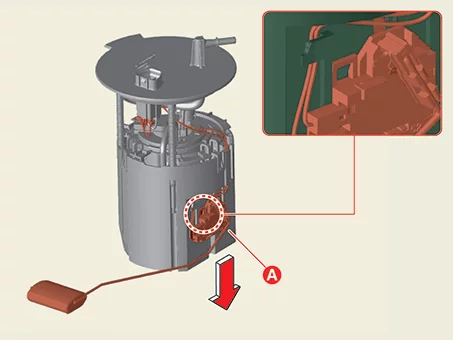
Remove the fuel pump module (A) from the fuel tank.
Installation
Install in reverse order of removal.
Be careful not to flow foreign matters into the fuel tank.
Check for fuel leaks after installation.
Fuel Sender Specification
Specification
Floating Position
Resistance (Ω)
Capacity [ℓ (U.S gal., U.S.qt., Imp.qt.)]
Full
14 - 16
47.5 (12.55, 50.19, 41.80)
1/2
85.5 - 87.5
25.6 (6.76, 27.05, 22.53)
Empty
298 - 305
4.0 (1.06, 4.23, 3.52)
Fuel Sender Components and Components Location
Component Location
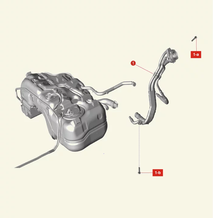
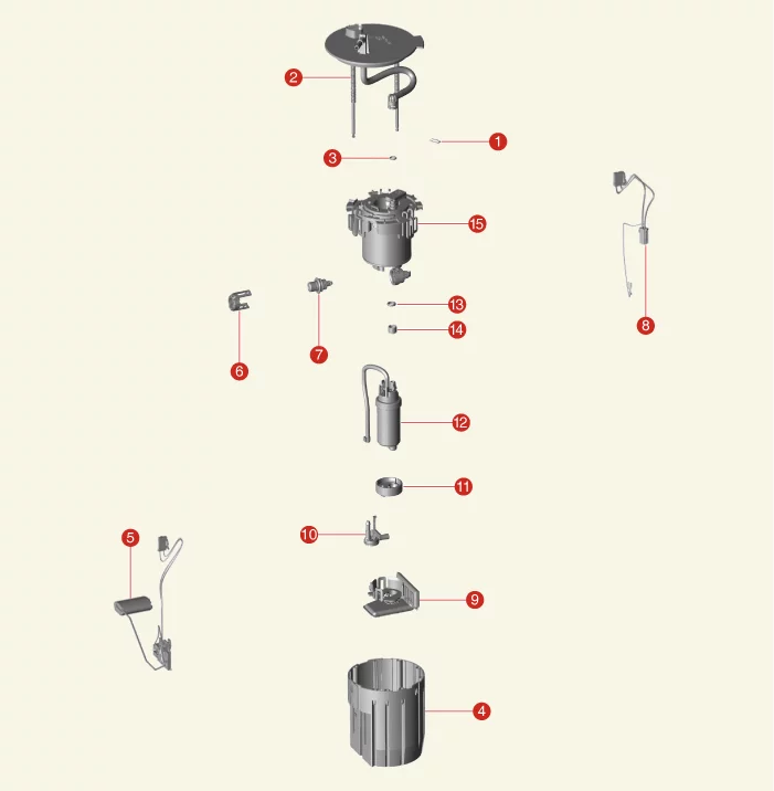
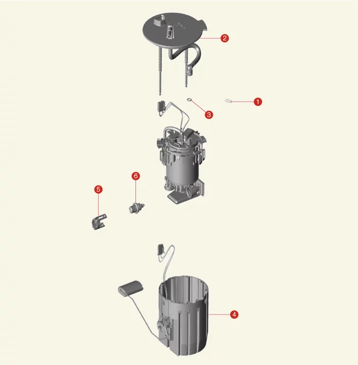
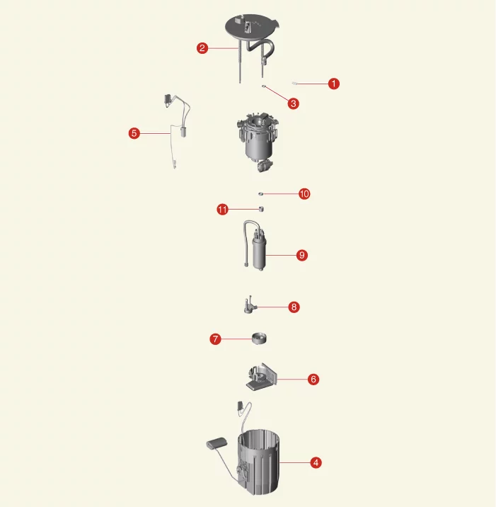
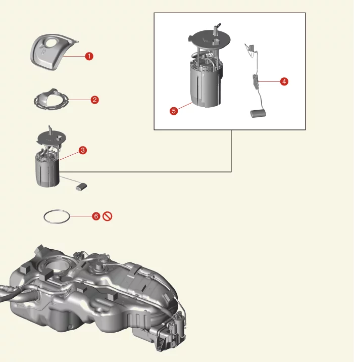
1. Service Cover 2. Plate Cover 3. Fuel Pump Module
Injector is an electronically controlled fuel injection device that is a solenoid valve that supplies accurately calculated fuel to the engine in the form of spray for optimal combustion for various engine operating conditions.
Engine Control Module (ECM) controls the amount of fuel injection to meet the air-fuel ratio (AFR) required by the engine control system by measuring the air-fuel ratio of intake air volume and exhaust gas and adjusting the injector operating time to improve fuel efficiency, engine performance and reduce the exhaust gas.
Injector On Vehicle Inspection
On Vehicle Inspection
The fuel delivery system can be more quickly diagnosed for problems by using the KDS (Refer to "DTC guide").
Self diagnosis : Inspect the Diagnostic Trouble Code (DTC) using the KDS (Refer to DTC guide when fault code is found)
Data analysis : Checking the system input/output data state (Data Analysis → System Selection → Engine)
Actuation test : Checking the system operation condition (Data Analysis → System Selection → Engine → Actuation test → Injector Disable-Cylinder 1 / 2 / 3 / 4)
Refer to the KDS screen for operating conditions and details
Component Inspection
Turn the IG OFF.
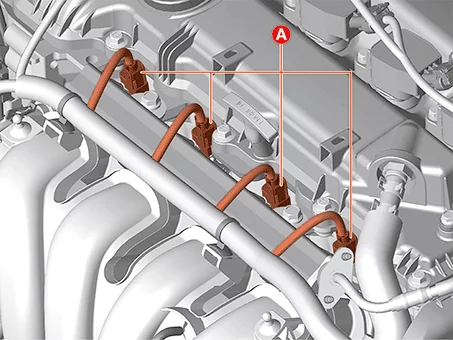
Disconnect the injector connector (A).
Measure resistance between the injector terminals 1 and 2.
Check that the resistance is within the specification.
Item
Specification
Coil resistance (Ω)
14.5 [20 °C]
Injector Removal and Installation
Removal
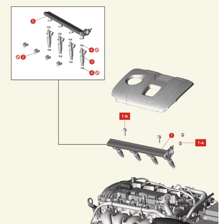
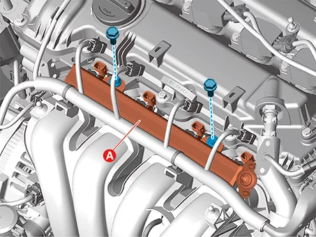
Remove the injector from the delivery pipe. (Refer to Fuel Delivery System - "Delivery Pipe")
Installation
Install in reverse order of removal.
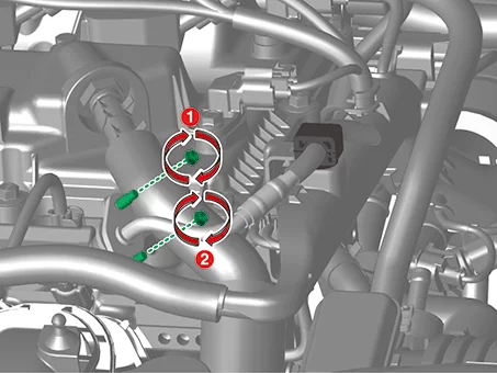
When installing the fuel feed tube to the delivery pipe, tighten the nuts alternately in order.
Tightening torque : 8.8 - 11,8 N·m
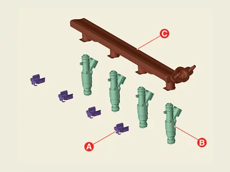
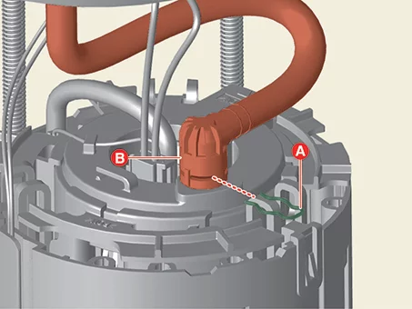
Replace the O-rings (A) and clip (B) with new one, when reusing the injector.