Intelligent Variable Transmission (IVT) System
Transmission Gear Oil Components and Components Location
In this manual: Intelligent Variable Transmission (IVT) System
109steps
~654min
4/5difficulty
Done 0 of 109
Contents:
Transmission Gear Oil Components and Components Location
Component
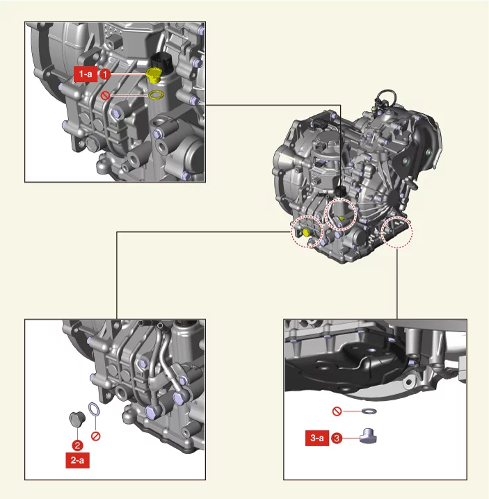
| 1. IVTF Filler Plug 1-a. 34.3 - 44 N·m 2. IVTF Level Plug 2-a. 34.3 - 44 N·m |
3. IVTF Drain Plug 3-a. 34.3 - 39 N·m |
Transmission Gear Oil Inspection
Inspection
Inspect the Intelligent Variable Transmission Fluid (IVTF) level
|
- Remove the air cleaner assembly. (Refer to Engine Mechanical System - "Air Cleaner")
- Remove the IVTF filler plug (A).
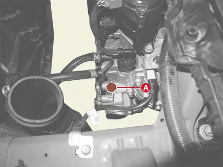
- Start the engine to warm up the IVTF.
Do not step on the brake and accelerator simultaneously to warm up the IVTF.
- Check by using KDS that the temperature of the IVTF is between 45 - 55 °C.
- Move the shift lever slowly from "P" to "D", then back to "P". Repeat this sequence two times and then move the shift lever to "P" range.
Pause in each range for more than 2 seconds. - Remove the engine room under cover. (Refer to Engine Mechanical System - "Engine Room Under Cover")
- Lift the vehicle and remove the IVTF level plug (A).
When removing the IVTF level plug, keep the vehicle on a level ground.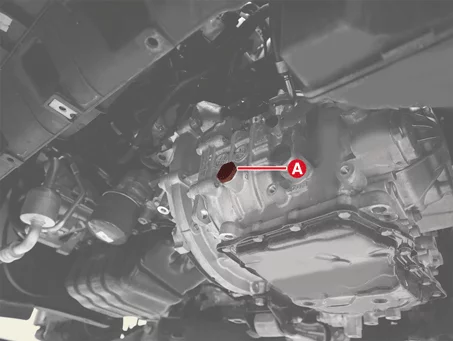
- Check the IVTF level.
Normal : 0.15 - 0.45 liters of IVTF flows out for 2 minutes Excessive (abnormal) : Over 0.45 liters of IVTF flows out for 2 minutes Insufficient (abnormal) : Below 0.15 liters of IVTF flows out for 2 minutes
If the IVTF level is too high or low, follow the instructions below.- Excessive : Drain until the IVTF flows out in a thin oil stream.
- Insufficient : Add until the IVTF flows out in a thin oil stream.
- Install the IVTF level plug (A).
Tightening torque : 34.3 - 44 N·m
The existing IVTF level plug gasket (A) must be replaced with a new one (do not reuse).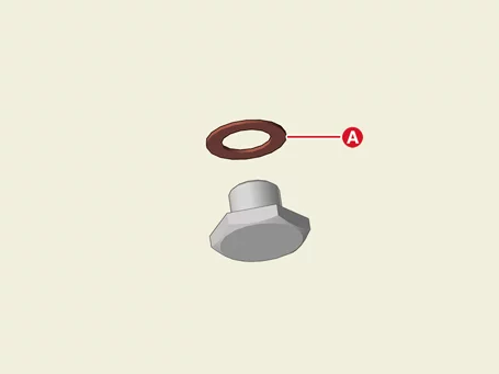
- Lower the vehicle and add the 0.3 liters (amount of oil drained during inspection) of SP-CVT1 through the IVTF filler hole.
- Be sure to use the genuine IVT Fluid (SP-CVT1)
- When replacing with non-genuine IVT fluid, bad shift and vibration may occur, causing damamge to the IVT.
- Non-genuine IVT fluid includes after market IVT fluid indicated as interchangeable with genuine Kia fluid.
- Install the IVTF filler plug (A).
Tightening torque : 34.3 - 44 N·m
The existing IVTF filler plug gasket (A) must be replaced with a new one (do not reuse).
Transmission Gear Oil Replacement
Replacement
- Remove the engine room under cover. (Refer to Engine Mechanical System - "Engine Room Under Cover")
- Remove the IVTF drain plug (A), allow the fluid to drain out and then reinstall the drain plug.
Tightening torque : 34.3 - 39 N·m
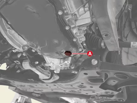
The existing IVTF drain plug gasket (A) must be replaced with a new one (do not reuse). - Remove the air cleaner assembly. (Refer to Engine Mechanical System - "Air Cleaner")
- Remove the IVTF filler plug (A).
- Fill the IVT with 3.5 - 5.0 liters of ATF SP-CVT1 through the IVTF filler hole.
- Be sure to use the genuine IVT Fluid (SP-CVT1)
- When replacing with non-genuine IVT fluid, bad shift and vibration may occur, causing damamge to the IVT.
- Non-genuine IVT fluid includes after market IVT fluid indicated as interchangeable with genuine Kia fluid.
- Perform the IVTF level inspection procedure. (Refer to Fluid - "Inspection")
Electric Oil Pump(EOP) Components and Components Location
Component Location
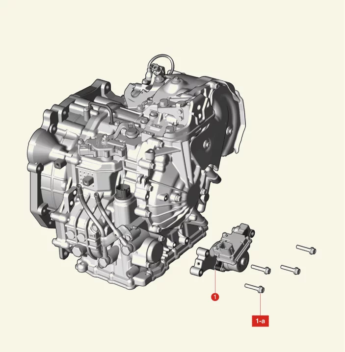
| 1. Electric Oil Pump (EOP) | 1-a. 19.6 - 26 N·m |
Electric Oil Pump(EOP) Removal and Installation
Removal
- Disconnect the battery negative ( - ) terminal.
- Remove the engine room under cover. (Refer to Engine Mechanical System - "Engine Room Under Cover")
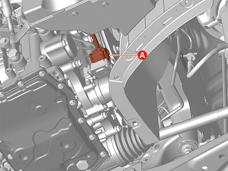
- Disconnect the EOP connector (A).
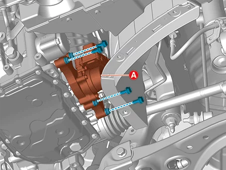
- Remove the EOP (A) after removing the bolts.
Tightening torque : 19.6 - 26 N·m
Installation
- Install in the reverse order of removal.
The existing O-ring (A) must be replaced with a new one (do not reuse).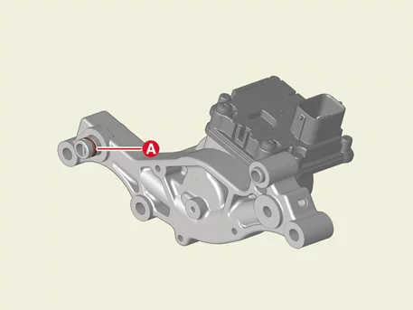
- Check the IVTF level after refilling the IVT with fluid. (Refer to Hydraulic System - "Fluid")
- Check for leakage of fluid from connection while the engine is starting and running.
Valve Body Components and Components Location
Component Location
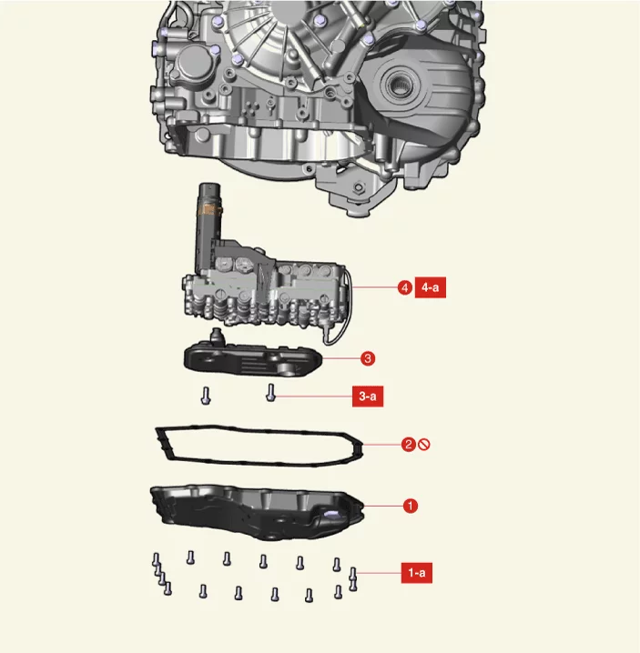
| 1. Valve Body Cover 1-a. 9.8 - 11,8 N·m 2. Valve Body Cover Gasket |
3. IVTF Filter 3-a. 9.8 - 11,8 N·m 4. Valve Body 4-a. 9.8 - 11,8 N·m |
Valve Body Description and Operation
Description
Valve Body
There are four indirect solenoid valves and one direct solenoid valve mounted to the valve body in the oil fan. Each indirect solenoid valve controls a driven pulley control valve (Secondary_VFS), drive pulley control valve (Primary_VFS), line pressure control valve (Line_VFS), damper clutch control solenoid valve (Damper/C_VFS). Direct solenoid valve controls drive/reverse clutch control solenoid valve (Clutch/Brake_VFS).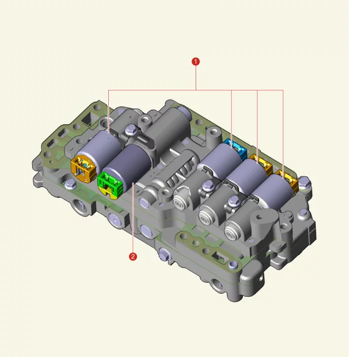
| 1. Indirect Control Solenoid Valve | 2. Direct Control Solenoid Valve |
Valve Body Removal
Removal
|
- Disconnect the battery negative ( - ) terminal.
- Remove the air cleaner assembly. (Refer to Engine Mechanical System - "Air Cleaner")
- Disconnect the IVT main connector (A).
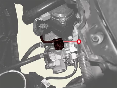
- Remove the engine room under cover. (Refer to Engine Mechanical System - "Engine Room Under Cover")
- Remove the IVTF drain plug (A), allow the fluid to drain out and then reinstall the drain plug.
Tightening torque : 34.3 - 39 N·m
- Intelligent variable transmission fluid (IVTF) can be reused. Collect it using a clean 10-liter beaker.
- The existing IVTF drain plug gasket (A) must be replaced with a new one (do not reuse).
- Remove the valve body cover (A) after removing the bolts.
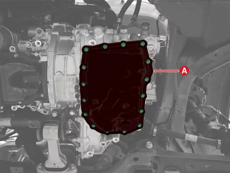
Be careful when removing the valve body cover because the remaining IVTF remains in the valve body cover. - Remove the valve body cover gasket (A).

- Remove the IVTF filter (A) after removing the bolts.
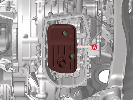
- Remove the valve body assembly (A) after removing the bolts.
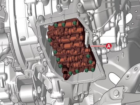
Be careful as residual IVTF may be drained when the valve body is removed.
Valve Body Installation
Installation
|
- Install the valve body assembly (A).
Tightening torque : 9.8 - 11,8 N·m
Check the installation condition of sealing (A) before installing the valve body.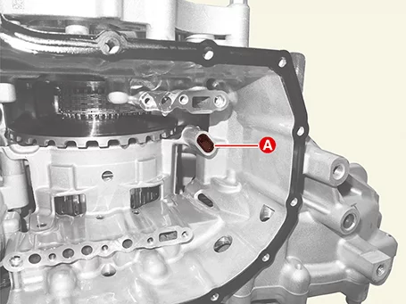
- Install the IVTF filter (A).
Tightening torque : 9.8 - 11,8 N·m
- Install the valve body cover in the following order.
- Remove foreign substances from the surface of the IVT case and valve body cover.
- Install the valve body cover (A) and gasket (B), and temporarily tighten the bolts except reference hole (C).

- The existing valve body cover gasket must be replaced with a new one (do not reuse).
- Tighten the bolts by hand to adjust the position of the gasket.
- Visually check the reference hole (A) to align the valve body cover hole with the gasket hole.
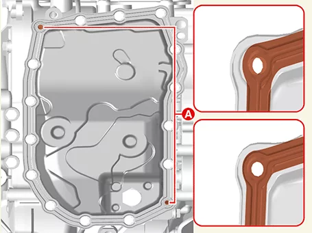
Tightening the bolts without aligning the valve body hole with the gasket hole may result in any IVTF leaks. - Tighten the remaining valve body cover mounting bolts except for the reference hole to the tightening torque.
Tightening torque : 9.8 - 11,8 N·m
Tighten the bolts diagonally alternately so that pressure is evenly applied. - Check that the valve body cover hole and gasket hole are properly aligned through the reference hole and tighten the bolt (A) to the reference hole.
Tightening torque : 9.8 - 11,8 N·m
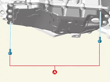
- Check the valve body cover for damage (crack, deformation, etc.) and clean the IVTF around the mounting area.
- Check the IVTF level after refilling the intelligent variable transmission with fluid. (Refer to Hydraulic System - "Fluid")
- Connect the IVT main connector (A).
- Install the air cleaner assembly. (Refer to Engine Mechanical System - "Air Cleaner")
- Check for leakage of IVT fluid from engine start.
- Install the engine room under cover. (Refer to Engine Mechanical System - "Engine Room Under Cover")
- Perform the procedures below after in replacing the valve body assembly.
- Clear the diagnostic trouble codes (DTC) using the KDS. (Disconnecting the battery negative terminal will not clear the DTCs. Clear DTCs using the KDS at all times.)
- Perform the resetting IVT transmission adaptive values using the KDS. (S/W Management → Intelligent Variable Transmission → Resetting Auto T/A Values)
Refer to the KDS screen for operating conditions and details.
- Perform the oil pressure characteristics input procedure using the KDS. (S/W Management → Intelligent Variable Transmission → Oil-pressure Characteristics Input)
Refer to the KDS screen for operating conditions and details.
- Perform the TCM adaptive values learning procedure. (Refer to IVT Control System - "Adjustment ")
Damper Clutch Control Solenoid Valve (D/C_VFS) Specification
Specification
| Item | Specification |
| Control type | Indirect control, N/L (Normal Low) |
| Control pressure [kPa (kgf/cm², psi)] | 0 - 956.14 ± 14.71 (0 - 9.75 ± 0.15, 0 - 138.68 ± 2.13) |
| Current (mA) | 0 - 1,100 |
| Coil resistance (Ω) | 5.0 - 5.6 |
Damper Clutch Control Solenoid Valve (D/C_VFS) Components and Components Location
Component Location
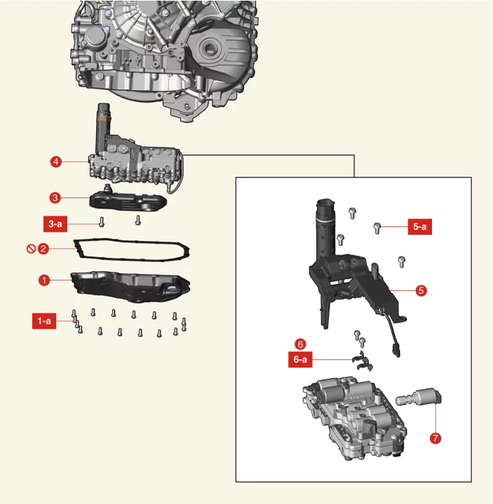
| 1. Valve Body Cover 1-a. 9.8 - 11,8 N·m 2. Valve Body Cover Gasket 3. IVTF Filter 3-a. 9.8 - 11,8 N·m |
4. Valve Body Assembly 4-a. 9.8 - 11,8 N·m 5. E-Module 5-a. 9.8 - 11,8 N·m 6. Support Bracket 6-a. 9.8 - 11,8 N·m 7. Damper Clutch Control Solenoid Valve |
Damper Clutch Control Solenoid Valve (D/C_VFS) On Vehicle Inspection
On Vehicle Inspection
- The Intelligent Variable Transmission system can be more quickly diagnosed for problems by using the vehicle diagnostic system (KDS). (Refer to "DTC guide")
- Self diagnosis : Inspection and display fault code (DTC)
- Sensor data : Checking the system input/output data state
- Forced operation : Check the system operating condition
- Additional function : Controlling other features including system option setting and zero point adjustment
Component Inspection
- Turn the IG "OFF".
- Disconnect the battery negative ( - ) terminal.
- Remove the air cleaner assembly. (Refer to Engine Mechanical System - "Air Cleaner")
- Disconnect the main connector (A).
- Measure the resistance between power terminal (10) and signal terminal (6).
Specification : 5.0 - 5.6 Ω
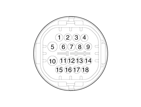
Damper Clutch Control Solenoid Valve (D/C_VFS) Removal and Installation
Removal
|
- Remove the E-Module. (Refer to IVT Control System - "E-Module")
- Remove the support bracket (A) after removing the bolts.
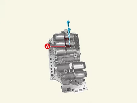
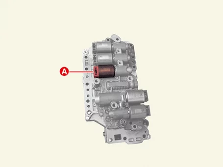
- Remove the damper clutch control solenoid valve (A).
Installation
|
- Install the damper clutch control solenoid valve (A).
- Install the support bracket (A).
Tightening torque : 9.8 - 11,8 N·m
- Install the E-Module. (Refer to IVT Control System - "E-Module")
- Perform the procedures below after in replacing the damper clutch control solenoid valve.
- Clear the diagnostic trouble codes (DTC) using the KDS. (Disconnecting the battery negative terminal will not clear the DTCs.)
- Perform the resetting IVT transmission adaptive values using the KDS. (S/W Management → Intelligent Variable Transmission → Resetting Auto T/A Values)
Refer to the KDS screen for operating conditions and details. - Perform TCM learning procedure. (Refer to IVT Control System - "Adjustment ")
Drive Pulley Control Solenoid Valve (Primary_VFS) Specification
Specification
| Item | Specification |
| Control type | Indirect control, N/H (Normal High) |
| Control pressure [kPa (kgf/cm², psi)] | 0 - 956.14 ± 14.71 (0 - 9.75 ± 0.15, 0 - 138.68 ± 2.13) |
| Current (mA) | 0 - 1,100 |
| Coil resistance (Ω) | 5.0 - 5.6 |
Drive Pulley Control Solenoid Valve (Primary_VFS) Components and Components Location
Component Location
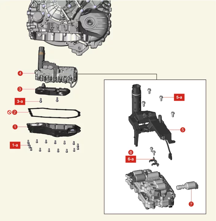
| 1. Valve Body Cover 1-a. 9.8 - 11,8 N·m 2. Valve Body Cover Gasket 3. IVTF Filter 3-a. 9.8 - 11,8 N·m |
4. Valve Body Assembly 4-a. 9.8 - 11,8 N·m 5. E-Module 5-a. 9.8 - 11,8 N·m 6. Support Bracket 6-a. 9.8 - 11,8 N·m 7. Drive Pulley Control Solenoid Valve |
Drive Pulley Control Solenoid Valve (Primary_VFS) On Vehicle Inspection
On Vehicle Inspection
- The Intelligent Variable Transmission system can be more quickly diagnosed for problems by using the vehicle diagnostic system (KDS). (Refer to "DTC guide")
- Self diagnosis : Inspection and display fault code (DTC)
- Sensor data : Checking the system input/output data state
- Forced operation : Check the system operating condition
- Additional function : Controlling other features including system option setting and zero point adjustment
Component Inspection
- Turn the IG "OFF".
- Disconnect the battery negative ( - ) terminal.
- Remove the air cleaner assembly. (Refer to Engine Mechanical System - "Air Cleaner")
- Disconnect the IVT main connector (A).
- Measure the resistance between power terminal (10) and signal terminal (8).
Specification : 5.0 - 5.6 Ω
Drive Pulley Control Solenoid Valve (Primary_VFS) Removal and Installation
Removal
|
- Remove the E-Module. (Refer to IVT Control System - "E-Module")
- Remove the support bracket (A) after removing the bolts.
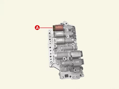
- Remove the drive pulley control solenoid valve (A).
Installation
|
- Install the drive pulley control solenoid valve (A).
- Install the support bracket (A).
Tightening torque : 9.8 - 11,8 N·m
- Install the E-Module. (Refer to IVT Control System - "E-Module")
- Perform the procedures below after replacing the drive pulley control solenoid valve with a new one.
- Clear the diagnostic trouble codes (DTC) using the KDS. (Disconnecting the battery negative terminal will not clear the DTCs.)
- Perform the resetting IVT transmission adaptive values using the KDS. (S/W Management → Intelligent Variable Transmission → Resetting Auto T/A Values)
Refer to the KDS screen for operating conditions and details. - Perform TCM learning procedure. (Refer to IVT Control System - "Adjustment ")
Driven Pulley Control Solenoid Valve (Secondary_VFS) Specification
Specification
| Item | Specification |
| Control type | Indirect control, N/H (Normal High) |
| Control pressure [kPa (kgf/cm², psi)] | 0 - 956.14 ± 14.71 (0 - 9.75 ± 0.15, 0 - 138.68 ± 2.13) |
| Current (mA) | 0 - 1,100 |
| Coil resistance (Ω) | 5.0 - 5.6 |
Driven Pulley Control Solenoid Valve (Secondary_VFS) Components and Components Location
Component Location
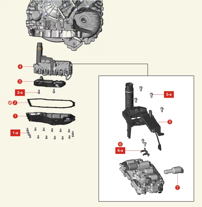
| 1. Valve Body Cover 1-a. 9.8 - 11,8 N·m 2. Valve Body Cover Gasket 3. IVTF Filter 3-a. 9.8 - 11,8 N·m |
4. Valve Body Assembly 4-a. 9.8 - 11,8 N·m 5. E-Module 5-a. 9.8 - 11,8 N·m 6. Support Bracket 6-a. 9.8 - 11,8 N·m 7. Driven Pulley Control Solenoid Valve |
Driven Pulley Control Solenoid Valve (Secondary_VFS) On Vehicle Inspection
On Vehicle Inspection
- The Intelligent Variable Transmission system can be more quickly diagnosed for problems by using the vehicle diagnostic system (KDS). (Refer to "DTC guide")
- Self diagnosis : Inspection and display fault code (DTC)
- Sensor data : Checking the system input/output data state
- Forced operation : Check the system operating condition
- Additional function : Controlling other features including system option setting and zero point adjustment
Component Inspection
- Turn the IG "OFF".
- Disconnect the battery negative ( - ) terminal.
- Remove the air cleaner assembly. (Refer to Engine Mechanical System - "Air Cleaner")
- Disconnect the IVT main connector (A).
- Measure the resistance between power terminal (10) and signal terminal (7).
Specification : 5.0 - 5.6 Ω
Driven Pulley Control Solenoid Valve (Secondary_VFS) Removal and Installation
Removal
|
- Remove the E-Module. (Refer to IVT Control System - "E-Module")
- Remove the support bracket (A) after removing the bolts.
- Remove the driven pulley control solenoid valve (A).
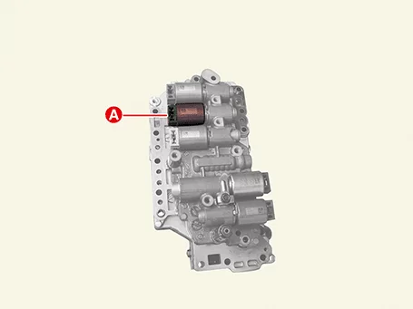
Installation
|
- Install the driven pulley control solenoid valve (A).
- Install the support bracket (A).
Tightening torque : 9.8 - 11,8 N·m
- Install the E-Module. (Refer to IVT Control System - "E-Module")
- Perform the procedures below after in replacing the driven pulley control solenoid valve.
- Clear the diagnostic trouble codes (DTC) using the KDS. (Disconnecting the battery negative terminal will not clear the DTCs.)
- Perform the resetting IVT transmission adaptive values using the KDS. (S/W Management → Intelligent Variable Transmission → Resetting Auto T/A Values)
Refer to the KDS screen for operating conditions and details. - Perform TCM learning procedure. (Refer to IVT Control System - "Adjustment ")
Drive/Reverse Clutch Control Solenoid Valve (Clutch/Brake_VFS) Specification
Specification
| Item | Specification |
| Control type | Direct control, N/H (Normal High) |
| Control pressure [kPa (kgf/cm², psi)] | 0 - 1569.06 (0 - 16.00, 0 - 227.57) |
| Current (mA) | 0 - 1,100 |
| Coil resistance (Ω) | 5.0 - 5.6 |
Drive/Reverse Clutch Control Solenoid Valve (Clutch/Brake_VFS) Components and Components Location
Component Location
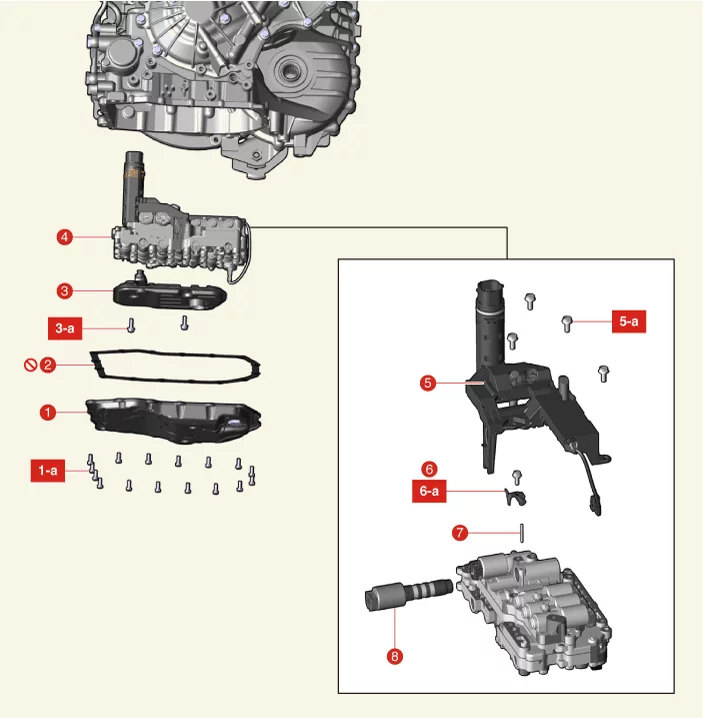
| 1. Valve Body Cover 1-a. 9.8 - 11,8 N·m 2. Valve Body Cover Gasket 3. IVTF Filter 3-a. 9.8 - 11,8 N·m |
4. Valve Body Assembly 4-a. 9.8 - 11,8 N·m 5. E-Module 5-a. 9.8 - 11,8 N·m 6. Support Bracket 6-a. 9.8 - 11,8 N·m 7. Roller 8. Drive/Reverse Clutch Control Solenoid Valve |
Drive/Reverse Clutch Control Solenoid Valve (Clutch/Brake_VFS) On Vehicle Inspection
On Vehicle Inspection
- The Intelligent Variable Transmission system can be more quickly diagnosed for problems by using the vehicle diagnostic system (KDS). (Refer to "DTC guide")
- Self diagnosis : Inspection and display fault code (DTC)
- Sensor data : Checking the system input/output data state
- Forced operation : Check the system operating condition
- Additional function : Controlling other features including system option setting and zero point adjustment
Component Inspection
- Turn the IG "OFF".
- Disconnect the battery negative ( - ) terminal.
- Remove the air cleaner assembly. (Refer to Engine Mechanical System - "Air Cleaner")
- Disconnect the IVT main connector (A).
- Measure the resistance between power terminal (5) and signal terminal (11).
Specification : 5.0 - 5.6 Ω
Drive/Reverse Clutch Control Solenoid Valve (Clutch/Brake_VFS) Removal and Installation
Removal
|
- Remove the E-Module. (Refer to IVT Control System - "E-Module")
- Remove the support bracket (A) after removing the bolts.
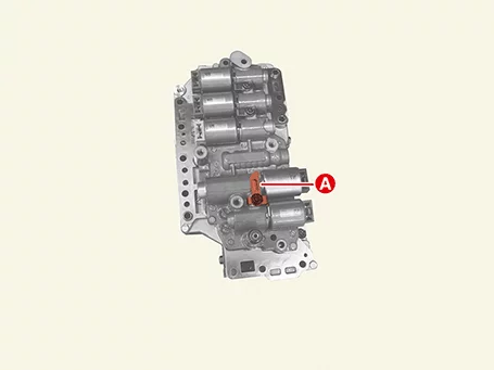
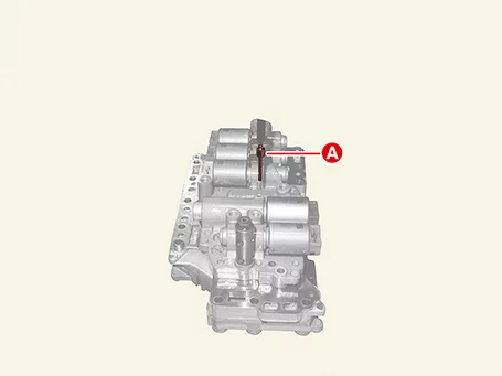
- Remove the roller (A) using a magnet.
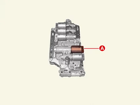
- Remove the drive/reverse clutch control solenoid valve (A).
Installation
|
- Install the drive/reverse clutch control solenoid valve (A).
- Check the oil pressure characteristics value (A) at the first before installing the solenoid valve.
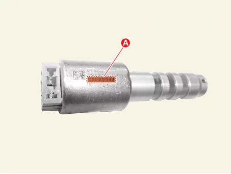
- If incorrect hydraulic characteristics are entered, the shift shock may occur during TCM learning, so note the engraved hydraulic values carefully.
- Check the oil pressure characteristics value (A) at the first before installing the solenoid valve.
- Install the roller (A).
- Install the support bracket (A).
Tightening torque : 9.8 - 11,8 N·m
- Install the E-Module. (Refer to IVT Control System - "E-Module")
- Perform the procedures below after in replacing the drive/reverse clutch control solenoid valve.
- Clear the diagnostic trouble codes (DTC) using the KDS. (Disconnecting the battery negative terminal will not clear the DTCs.)
- Perform the resetting IVT transmission adaptive values using the KDS. (S/W Management → Intelligent Variable Transmission → Resetting Auto T/A Values)
Refer to the KDS screen for operating conditions and details. - Perform the oil pressure characteristics input procedure using the KDS. (S/W Management → Intelligent Variable Transmission → Oil-pressure Characteristics Input)
Refer to the KDS screen for operating conditions and details. - Perform TCM learning procedure. (Refer to IVT Control System - "Adjustment ")
Line Pressure Control Solenoid Valve (LINE_VFS) Specification
Specification
| Item | Specification |
| Control type | Indirect control, N/H (Normal High) |
| Control pressure [kPa (kgf/cm², psi)] | 0 - 956.14 ± 14.71 (0 - 9.75 ± 0.15, 0 - 138.68 ± 2.13) |
| Current (mA) | 0 - 1,100 |
| Coil resistance (Ω) | 5.0 - 5.6 |
Line Pressure Control Solenoid Valve (LINE_VFS) Components and Components Location
Component Location

| 1. Valve Body Cover 1-a. 9.8 - 11,8 N·m 2. Valve Body Cover Gasket 3. IVTF Filter 3-a. 9.8 - 11,8 N·m |
4. Valve Body Assembly 4-a. 9.8 - 11,8 N·m 5. E-Module 5-a. 9.8 - 11,8 N·m 6. Support Bracket 6-a. 9.8 - 11,8 N·m 7. Line Pressure Control Solenoid Valve |
Line Pressure Control Solenoid Valve (LINE_VFS) On Vehicle Inspection
On Vehicle Inspection
- The Intelligent Variable Transmission system can be more quickly diagnosed for problems by using the vehicle diagnostic system (KDS). (Refer to "DTC guide")
- Self diagnosis : Inspection and display fault code (DTC)
- Sensor data : Checking the system input/output data state
- Forced operation : Check the system operating condition
- Additional function : Controlling other features including system option setting and zero point adjustment
Component Inspection
- Turn the IG "OFF".
- Disconnect the battery negative ( - ) terminal.
- Remove the air cleaner assembly. (Refer to Engine Mechanical System - "Air Cleaner")
- Disconnect the IVT main connector (A).
- Measure the resistance between power terminal (5) and signal terminal (12).
Specification : 5.0 - 5.6 Ω
Line Pressure Control Solenoid Valve (LINE_VFS) Removal and Installation
Removal
|
- Remove the E-Module. (Refer to IVT Control System - "E-Module")
- Remove the support bracket (A) after removing the bolts.
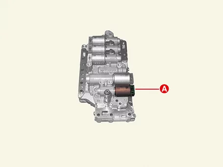
- Remove the line pressure control solenoid valve (A).
Installation
|
- Install the line pressure control solenoid valve (A).
- Install the support bracket (A).
Tightening torque : 9.8 - 11,8 N·m
- Install the E-Module. (Refer to IVT Control System - "E-Module")
- Perform the procedures below after in replacing the line pressure control solenoid valve.
- Clear the diagnostic trouble codes (DTC) using the KDS. (Disconnecting the battery negative terminal will not clear the DTCs.)
- Perform the resetting IVT transmission adaptive values using the KDS. (S/W Management → Intelligent Variable Transmission → Resetting Auto T/A Values)
Refer to the KDS screen for operating conditions and details. - Perform TCM learning procedure. (Refer to IVT Control System - "Adjustment ")
Pressure Filter Removal and Installation
Removal
- Remove the engine room under cover. (Refer to Engine Mechanical System - "Engine Room Under Cover")
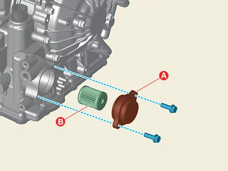
- Remove the pressure filter cover (A) and pressure filter (B) after removing the bolts.
Tightening torque : 19.6 - 26 N·m
- When removing the cover, the pressure filter is also removed.
- When the cover is removed, a small amount of IVTF is discharged.
Installation
- Install in the reverse order of removal.
Before installing the pressure filter cover, check the O-ring (A) is installed properly.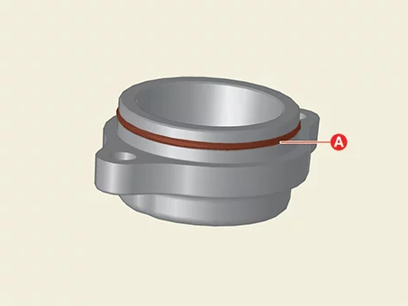
- Perform the IVTF level inspection procedure. (Refer to Transmission Gear Oil - "Inspection")
Was this page helpful?