Restraint
SRSCM
In this manual: Restraint
30steps
~180min
4/5difficulty
Done 0 of 30
Contents:
Components and Components Location
Component
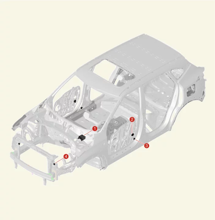
| 1. Supplemental Restraint System Control Module (SRSCM) 2. Pressure type Side Impact Sensor (P-SIS) |
3. Acceleration type Side Impact Sensor (A-SIS) 4. Front Impact Sensor (FIS) |
On Vehicle Inspection
On Vehicle Inspection
Diagnosis with KDS
- The airbag system can be more quickly diagnosed for problems with the KDS (Refer to "DTC guide").
- Self diagnosis : Inspect the Diagnostic Trouble Code (DTC) with the KDS. (Refer to DTC guide when fault code is found.)
- S/W Management : Controlling other features including system option setting and zero point adjustment. (S/W Management → Airbag → ACU Variant Coding)
Refer to the KDS screen for operating conditions and details.
SRS Control Module (SRSCM) Description and Operation
Description
- The Supplemental Restraint System Control Module (SRSCM) determines whether and when to deploy the airbag module and the seat Belt Pretensioner (BPT).
- It supplies the power required for deployment at the time of deployment of the airbag module or seat Belt Pretensioner (BPT).
- It also performs the self-diagnosis function of Supplemental Restraint System (SRS).
SRS Control Module (SRSCM) Connector And Terminal Function
Connector And Terminal Function
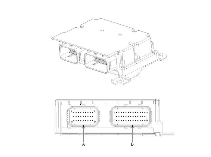
| Pin No | Connector A | Connector B |
| 1 | IG 1 | Ground ( - ) |
| 2 | Driver's side front impact sensor (High) | Driver's side seat belt pretensioner (High) |
| 3 | Driver's side front impact sensor (Low) | Driver's side seat belt pretensioner (Low) |
| 4 | Driver airbag #1 (High) | Driver's side belt anchor pretensioner (Low) |
| 5 | Driver airbag #1 (Low) | Driver's side belt anchor pretensioner (High) |
| 6 | Passenger airbag #1 (Low) | Driver's side airbag (High) |
| 7 | Passenger airbag #1 (High) | Driver's side airbag (Low) |
| 8 | - | Passenger's side airbag (Low) |
| 9 | - | Passenger's side airbag (High) |
| 10 | Crash signal output | Driver's side side impact sensor (High) |
| 11 | Passenger's side front impact sensor (High) | Driver's side side impact sensor (Low) |
| 12 | Passenger's side front impact sensor (Low) | Passenger's side side impact sensor (Low) |
| 13 | Driver airbag #2 (High) | Passenger's side side impact sensor (High) |
| 14 | Driver airbag #2 (Low) | Passenger's side seat belt buckle sensor (High) |
| 15 | Passenger airbag #2 (Low) | Passenger's side seat belt pretensioner (High) |
| 16 | Passenger airbag #2 (High) | Passenger's side seat belt pretensioner (Low) |
| 17 | P-CAN (High) | Passenger's side seat belt anchor pretensioner (Low) |
| 18 | P-CAN (Low) | Passenger's side seat belt anchor pretensioner (High) |
| 19 | Battery ( + )(KL30) | Driver's side curtain airbag (High) |
| 20 | Passenger's side airbag OFF lamp (Telltale) | Driver's side curtain airbag (Low) |
| 21 | - | Passenger's side curtain airbag (Low) |
| 22 | - | Passenger's side curtain airbag (High) |
| 23 | - | Driver's side door side impact sensor (High) |
| 24 | Passenger airbag #3 vent (Low) | Driver's side door side impact sensor (Low) |
| 25 | Passenger airbag #3 vent (High) | Passenger's side door side impact sensor (Low) |
| 26 | C-CAN (High) | Passenger's side door side impact sensor (High) |
| 27 | C-CAN (Low) | - |
| 28 | Passenger's side rear seat belt retractor pretensioner (High) | |
| 29 | Passenger's side rear seat belt retractor pretensioner (Low) | |
| 30 | Driver's side rear seat belt retractor pretensioner (Low) | |
| 31 | Driver's side rear seat belt retractor pretensioner (High) | |
| 32 | - | |
| 33 | - | |
| 34 | - | |
| 35 | - | |
| 36 | - | |
| 37 | - | |
| 38 | - | |
| 39 | - |
SRS Control Module (SRSCM) Removal
Removal
- Disconnect the battery negative ( - ) terminal.
After disconnecting the battery negative ( - ) terminal, wait at least 3 minutes and 30 seconds.
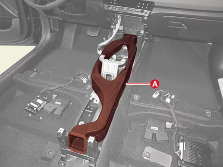
- Remove the floor console assembly. (Refer to Body - "Floor Console Assembly")
- Remove the rear air duct (A).
- Disconnect the supplemental restraint system control module connectors (A) by pulling the connector lock lever.
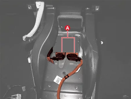
- Remove the supplemental restraint system control module (A) after removing the bolts.
Tightening torque : 10.8 - 13,7 N·m
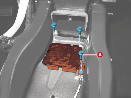
Do not damage the Supplemental Restraint System Control Module (SRSCM) connector.
SRS Control Module (SRSCM) Installation
Installation
- Install in reverse order of removal.
In the case of the SRSCM with the rollover detection function applied, the airbag may be deployed due to the movement generated during the installation, so do not install the SRSCM while the battery is connected or less than 3 minutes and 30 seconds after the battery is disconnected.
Be sure to keep the torque specifications presented in shop manuals. Otherwise, it could lead to the malfunction of airbag system. - After installing the SRSCM, make sure that the airbag system operates normally.
When the IG is on, the airbag warning lamp should turns off after turning on for 3 - 6 seconds. - When replaced the Supplemental Restraint System Control Module (SRSCM) perform the "ACU Variant Coding" with the KDS. (S/W Management → Airbag → ACU Variant Coding)
Refer to the KDS screen for operating conditions and details.
Front Impact Sensor (FIS) Description and Operation
Description
- One Front Impact Sensor (FIS) is installed on the each of left and right sides of the engine room at the top of the Front End Module
- When event of a head-on collision, the Supplemental Restraint System Control Module (SRSCM) uses the front impact sensor (FIS) signal to determine whether and when to deploy the Driver Airbag (DAB), front Passenger Airbag (PAB), and seat Belt Pretensioner (BPT).
Front Impact Sensor (FIS) Removal and Installation
Removal
- Disconnect the battery negative ( - ) terminal.
After disconnecting the battery negative ( - ) terminal, wait at least 3 minutes and 30 seconds. - Disconnect the front impact sensor connector (A).
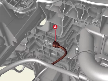
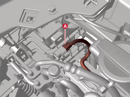
- Remove the front impact sensor (A) after removing the nut.
Tightening torque : 6.9 - 7,8 N·m
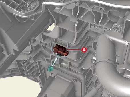
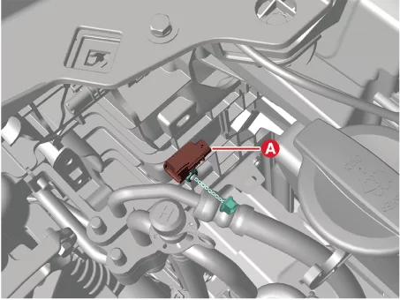
Installation
- Install in reverse order of removal.
Be sure to keep the torque specifications presented in shop manuals. Otherwise, it could lead to the malfunction of airbag system. - After installing the front impact sensor, make sure that the system operates normally.
When the IG is on, the airbag warning lamp should turns off after turning on for 3 - 6 seconds.
Side Impact Sensor (SIS) Description and Operation
Description
- The Side Impact Sensor (SIS) is installed one each at the center of the left and right front door modules and near the left and right center pillars to detect side collisions of the vehicle.
- The SIS consists of the Pressure type Front Side Impact Sensor sensing the collision pressure, the Acceleration type Front Side Impact Sensor sensing the front side collision acceleration.
- In the event of a side collision, the Supplemental Restraint System Control Module (SRSCM) determines whether and when to deploy the Side Airbag (SAB) module by using the side collision detection sensor signal.
Side Impact Sensor (SIS) Removal and Installation
Removal
Pressure type Side Impact Sensor (P-SIS)- Disconnect the battery negative ( - ) terminal.
After disconnecting the battery negative ( - ) terminal, wait at least 3 minutes and 30 seconds. - Remove the front door trim. (Refer to Body - "Front Door Trim")
- Disconnect the pressure type side impact sensor (P-SIS) connector (A).
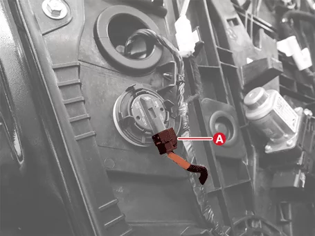
- Remove the pressure type side impact sensor (P-SIS) (A) by turning it in the direction of the arrow.
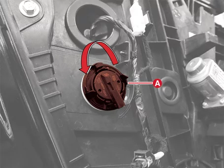
- Disconnect the battery negative ( - ) terminal.
After disconnecting the connector, wait at least 3 minutes and 30 seconds. - Remove the center pillar lower trim. (Refer to Body - "Center Pillar Trim")
- Disconnect the acceleration type side impact sensor (A-SIS) connector (A).
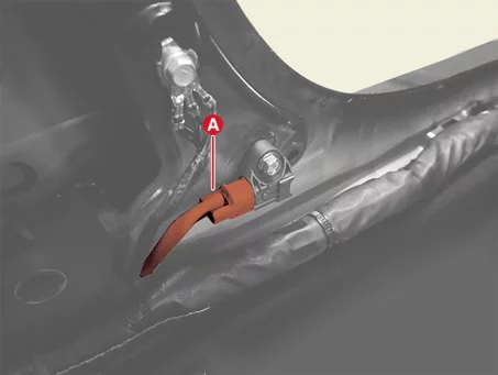
- Remove the acceleration type side impact sensor (A-SIS) (A) after removing the bolt.
Tightening torque : 8.8 - 9,8 N·m
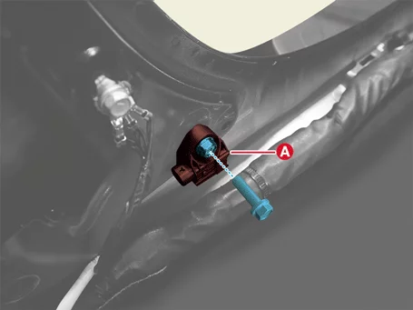
Installation
- Install in reverse order of removal.
Be sure to keep the torque specifications presented in shop manuals. Otherwise, it could lead to the malfunction of airbag system. - After installing the sensor, make sure that the system operates normally.
When the IG is on, the airbag warning lamp should turns off after turning on for 3 - 6 seconds.
Occupant Detecting System (ODS) Description and Operation
Description
- For normal operation of the passenger side airbag, the Supplemental Restraint System Control Module (SRSCM) detects a Diagnostic Trouble Code (DTC) of the occupant detective system unit.
- The Occupant Detective System (ODS) sensor mounted on the passenger seat divides the passenger into a child protection device and an adult and sends passenger information to the SRSCM.
- The SRSCM decides whether the Passenger Airbag (PAB) deploys by using the passenger information and crash signal.
Occupant Detecting System (ODS) Removal
Removal
[Occupant Detection System Mat]
- Remove the passenger side front seat cushion pad (A). (Refer to Body - "Front Seat Cushion Cover")
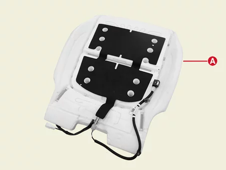
When replacing the occupant detection sensor mat (A) the front seat cushion assembly is replaced.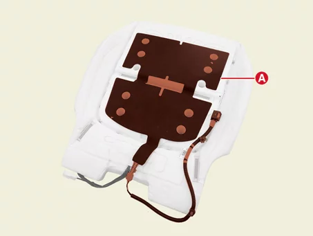
[Occupant Detection System Unit]
- Remove the passenger side front seat assembly. (Refer to Body - "Front Seat Assembly")
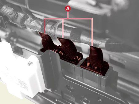
- Disconnect the occupant detection system unit connector (A).
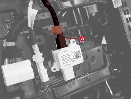
- Disconnect the seat heating and ventilation unit connectors (A).
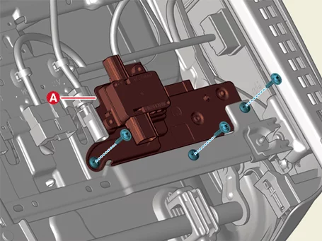
- Remove the occupant detection system unit bracket (A) after removing the screws.
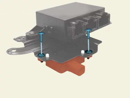
- Remove the occupant detection system unit (A) after removing the screws.
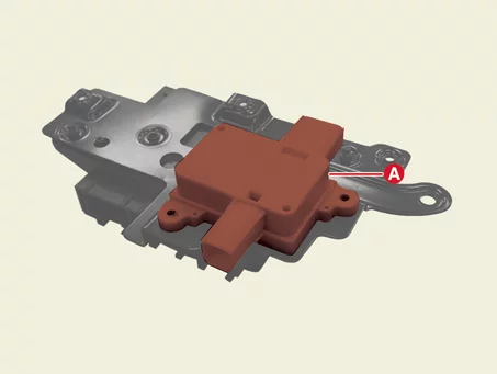
Occupant Detecting System (ODS) Installation
Installation
Occupant Detective System (ODS)- Install in reverse order of removal.
When the turned IG ON, the airbag warning lamp should be turned on and off for 3 to 6 seconds.- The passenger side airbag OFF indicator turns on the below when the occupant detective sensor unit and the passenger's side airbag are operating normally.
- The front passenger airbag warning light turns on for 4 seconds when turned IG ON.
- The front passenger airbag warning light turns on for 3 seconds when turned IG OFF.
- Perform the occupant detective sensor initialization wite the KDS. (S/W Management → Occupant Detective Sensor → Body Sensor Reset)
After reset the occupant detective sensor unit, delete the Supplemental Restraint System Control Module (SRSCM) Diagnostic Trouble Code (DTC).
Refer to the KDS screen for operating conditions and details.
Was this page helpful?