Engine and Transaxle Assembly
Repair Procedures
Removal and Installation
Disconnect the negative battery cable.
Remove the engine cover.
(See Engine and Transaxle Assembly - Engine Cover)
Remove the engine room cover.
(See Engine and Transaxle Assembly - Under Hood)
Drain the engine coolant.
(Refer to Cooling System - "Engine Coolant")
Recover the refrigerant, then disconnect the discharge line (A) and suction line (B).
(Refer to Heating, Ventilation and Air Conditioning - "Compressor").


Remove the air cleaner assembly.
(See Intake and Exhaust System - Air Cleaner)
Disconnect the upper radiator hose (A).

Disconnect the radiator lower hose (A).

Disconnect the ATF cooler hoses (A).

Remove the intercooler hose and pipe.
Disconnect the EGR valve connector (A) and vacuum hose (B).

Remove the intake hose and intercooler tube assembly (A).
Tightening Torque
Nuts (B):
14,7–19.6 N·m
Nut (C):
14,7–19.6 N·m

Disconnect the boost pressure sensor connector (A).
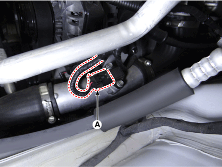
Remove the intercooler outlet hose and pipe assembly (A).
Tightening Torque
Hose clamp:
4.9–6.9 N·m (0.5–0.7 kgf·m, 3.6–5.1 ft-lbf, 43.4–60.8 in-lbf)
(If equipped with a cap, tighten until the cap is removed.)
Bolt:
14,7–19.6 N·m

Disconnect the fuel hose (A) and the purge control solenoid valve (PCSV) hose (B).
Disconnect the brake booster vacuum hose (C).

Disconnect the heater hose (A).

Remove the right hood seal cover (A).

Remove the engine room cover (A).
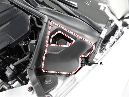
Remove the LH hood seal cover (A).

Remove the upper hood cover.
(Refer to Body (Interior and Exterior) - "Hood Panel")
Disconnect the wiring connector and wire harness from the engine room.
Remove the fuse box cover (A).

Disconnect the front control connector (A).
Disconnect the starter ground cable (B).
Tightening torque: 7.8–9.8 N·m
Disconnect the generator ground cable (C).
Tightening torque: 7.8–9.8 N·m
Remove the wiring protector (D).
Tightening torque:
4.9–7.8 N·m (0.5–0.8 kgf·m, 3.6–5.8 ft·lbf, 43.4–69.4 in·lbf)

Disconnect the ECM connector (A) and the TCM connector (B).
Remove the wiring protector (C).
Tightening torque:
4.9–7.8 N·m (0.5–0.8 kgf·m, 3.6–5.8 ft·lbf, 43.4–69.4 in·lbf)

Disconnect the R-MDPS connector (A).
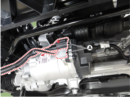
Disconnect the engine ground cable (A).

Disconnect the parking cable from the automatic transmission.
(Refer to Automatic Transmission System - Automatic Transmission)
Remove the front muffler.
(See Intake and Exhaust System - Muffler)
Remove the propeller shaft from the automatic transmission.
(Refer to Drive Shaft and Axle - "Propeller Shaft")
Remove the front wheel.
Disconnect the universal joint assembly from the shaft joint.
(Refer to Steering System - "Steering Column and Shaft")
Remove the tie rod end ball joint from the steering knuckle.
(Refer to Steering System - Steering Gear Box)
Remove the stabilizer bar link from the front shock absorber assembly.
(Refer to Suspension System - Front Stabilizer Bar).
Remove the front propeller shaft from the front axle. (If equipped with all-wheel drive system)
(Refer to Drive Shaft and Axle — "Front Propeller Shaft")
Remove the side arm and clamp arm from the subframe.
(Refer to Suspension System - Front Lower Arm).
Disconnect the automatic transmission ground cable (A).

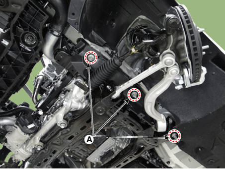
Support the engine and transmission with a jack, then remove the subframe mounting bolts (A).
Tightening torque: 176.5–196 N·m
[LH]
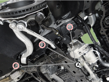
[RH]
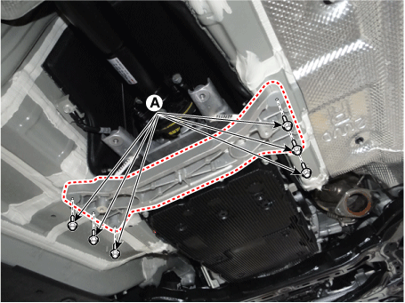
Remove the transaxle mounting bracket bolts (A).
Tightening torque: 58.8–74 N·m

Remove the engine and transaxle assembly by lifting the vehicle.

Remove the engine assembly from the subframe.
Remove the left/right engine mount insulator nut (A).
Tightening torque: 63.7–83 N·m
[LH]

[RH]

Attach the engine hoist to the engine hanger hole.
Remove the engine assembly from the subframe by raising the engine hoist.

Installation
Install the remaining parts in the reverse order of removal.
Do the following:
Adjust the shift cable.
Fill the engine with engine oil.
Fill the transmission with fluid.
Fill the radiator and the coolant reservoir with engine coolant.
Inspect for fuel leaks.
After assembling the fuel line, turn the ignition switch ON (do not crank the starter) so that the fuel pump operates for approximately two seconds and the fuel line is pressurized.
Repeat this operation two or three times, then check for fuel leaks at all points of the fuel line.
Bleed air from the cooling system.
Start the engine and let it run until it warms up (until the radiator fan cycles 3 or 4 times).
Turn the engine off. Check the radiator level and add coolant if necessary. This allows air trapped in the cooling system to be removed.
Test yourself
A quick Kia Stinger CK quiz: every answer comes with an explanation and a link to the manual page.