Timing Chain Guide Assembly
Repair Procedures
Removal
Remove the cylinder head cover.
(Refer to Cylinder Head Assembly - "Cylinder Head Cover")
Turn the crankshaft pulley and align its groove with the timing mark on the timing chain cover to set the No. 1 cylinder piston to top dead center on the compression stroke.

Remove the timing chain cover.
(See Valve Timing - "Timing Chain Cover")
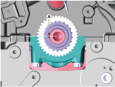
Make sure the crankshaft key (A) is aligned with the mating surface of the main bearing cap. As a result, the No. 1 cylinder piston is at top dead center on the compression stroke.
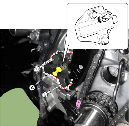
Release the ratchet by pulling the link down with a thin rod. Compress the piston, then insert the stopper pin into the ratchet hole to hold the compressed piston. Remove the timing chain tensioner (A).
Remove the timing chain tensioner arm (A).

Remove the timing chain guide (A).

Remove the timing chain (A).

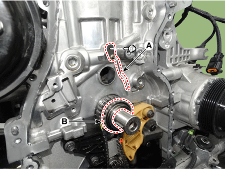
Remove the timing chain oil nozzle (A) and the crankshaft sprocket (B).
Remove the balance shaft chain.
(Refer to Lubrication System - Balance Shaft and Oil Pump)
Inspection
Hydraulic tensioner sprocket, chain guide, tensioner arm, timing chain
Inspect the CVVT sprocket and the crankshaft sprocket teeth for abnormal wear, cracks or damage. Replace if necessary.
Check the contact surface of the chain tensioner lever and guide for abnormal wear, cracks, or damage.
Replace if necessary.
Inspect the hydraulic tensioner for plunger movement and ratchet operation. Replace if necessary.
Check the timing chain for elongation, excessive wear, or damage. Replace if necessary.
Installation
Install the balance shaft chain.
(Refer to Lubrication System - Balance Shaft and Oil Pump)
Install the crankshaft chain sprocket (B) and the timing chain oil nozzle (A).
Tightening torque: 7.8 – 9.8 N·m
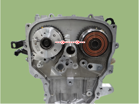
Position the crankshaft so that the crankshaft key (A) is aligned with the mating surface of the main bearing cap. Install the intake and exhaust camshaft assemblies so that the TDC marks (B) on the intake and exhaust CVVT sprockets are aligned with the upper surface of the cylinder head. As a result, the No. 1 cylinder piston is at top dead center on the compression stroke.
Install the timing chain guide (A).
Tightening torque: 9.8–11.8 N·m
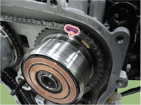
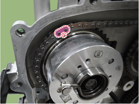

Install the timing chain. To install the timing chain without slack, perform the following procedure for each shaft (camshaft, crankshaft).
Crankshaft sprocket (A) → Timing chain guide (B) → Intake CVVT sprocket (C) → Exhaust CVVT sprocket (D).
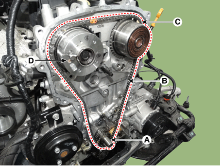
Install the timing chain tensioner arm (A).
Tightening torque: 9.8–11.8 N·m
Install the automatic timing chain tensioner (A) and remove the stopper pin.
Tightening torque: 9.8–11.8 N·m
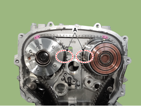
After rotating the crankshaft 2 turns in the normal direction (clockwise when viewed from the front), make sure the TDC marks (A) on the intake and exhaust CVVT sprockets are aligned with the upper surface of the cylinder head.
Install the timing chain cover.
(See Valve Timing - "Timing Chain Cover")
Install the cylinder head cover.
(Refer to Cylinder Head Assembly - "Cylinder Head Cover")
Add all necessary fluids and check for leaks. Connect the KDS/GDS. Check for codes, notes and clear them. Recheck.
Test yourself
A quick Kia Stinger CK quiz: every answer comes with an explanation and a link to the manual page.