Timing Chain Cover
Repair Procedures
Removal
Disconnect the negative battery cable.
Remove the engine cover.
(See Engine and Transaxle Assembly - Engine Cover)
Remove the engine compartment under cover (front).
(See Engine and Transaxle Assembly - Under Hood)
Remove the drive belt.
(See Drive Belt System - Drive Belt)
Remove the water pump pulley.
(See Cooling System - "Water Pump")
Remove the drive belt tensioner.
(Refer to Drive Belt System - "Drive Belt Tensioner")
Remove the crankshaft damper pulley.
(See Drive Belt System - "Crankshaft Damper Pulley")
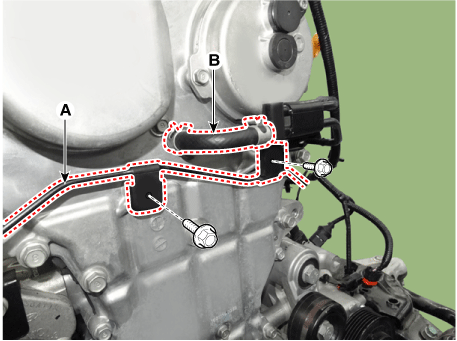
Remove the vacuum hose (A), then disconnect the lower vent hose (B).
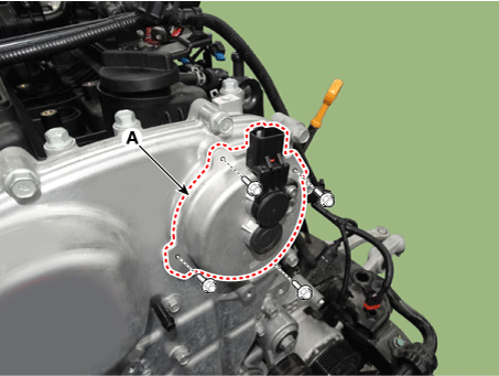
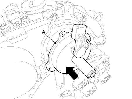
Remove the E-CVVT cover (A).
Remove the oil pan.
(See Lubrication System - Oil Pan)
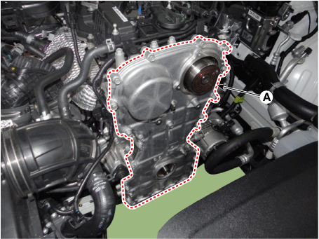
Remove the timing chain cover (A) by carefully prying between the cylinder head and cylinder block.
Inspection
Check for oil leakage inside the E-CVVT cover.
If oil leaks inside the E-CVVT cover, replace the E-CVVT cover.
Check the connector brush for wear.
If the brush is worn, replace the E-CVVT cover assembly.
Installation
Install the timing chain cover.
Using a gasket scraper, remove all old gasket material from the sealing surfaces.
The sealant contact surfaces on the timing chain cover and mating parts (cylinder head, cylinder block and ladder frame) must be cleaned of engine oil, etc.
Before installing the timing chain cover, apply liquid sealant Loctite 5900H or equivalent to the gap between the camshaft front bearing cap, cylinder head and cylinder block. The parts must be assembled within 5 minutes after applying the sealant.
Bead width: 2.0–3.0 mm (0.08–0.12 in.)
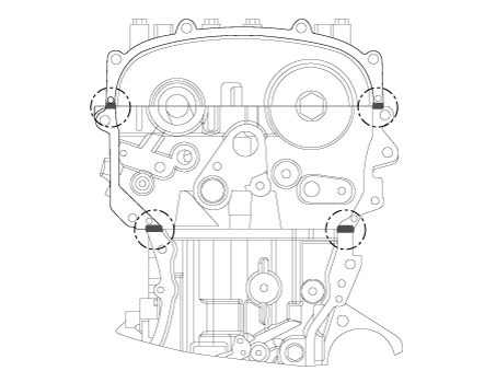
After applying liquid sealant Loctite 5900H or equivalent to the timing chain cover.
The parts must be assembled within 5 minutes after applying the sealant. Apply a continuous bead of sealant to prevent any oil leakage path.
Bead width: 2.0–3.0 mm (0.08–0.12 in.)
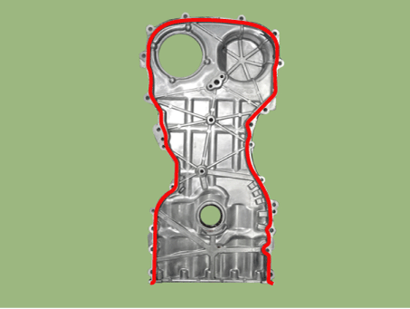
Use the locating pins on the cylinder block and the holes in the timing chain cover as a reference for assembly. The timing chain cover must be installed in the correct position.
Tightening Torque
M6 x 25 bolt:
9,8–11.8 N·m
M8 x 28 bolt:
18,6–23 N·m
Install the front oil seal.
(Refer to Valve Timing System - "Front Oil Seal")
Install the drive belt tensioner.
(Refer to Drive Belt System - "Drive Belt Tensioner")
Remove it by breaking the center of the E-CVVT engine connector (A).
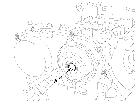
Clean the mounting surface of the E-CVVT engine plug (A) using oil cleaner.
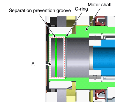
When reusing the E-CVVT cover, inspect the following items.
If there are signs of leakage inside the E-CVVT cover, replace it with a new one.
Check whether the connecting brush is worn.
Specification: More than 5 mm (0.1969 in.)
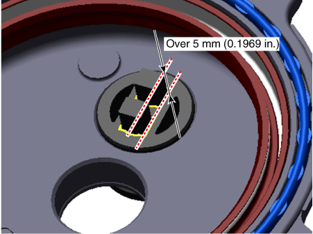
If the dimension is below specification, replace the E-CVVT cover with a new one.
Check the oil seal (A) for damage and replace the damaged E-CVVT cover with a new one.
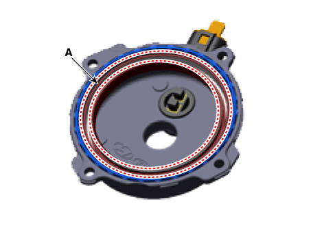
After inspecting the E-CVVT, if no problems are found, replace the O-ring (A) with a new one.
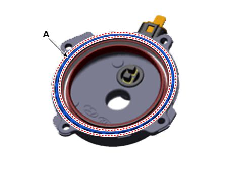
Install the E-CVVT cover.
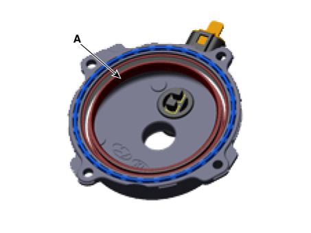
Apply engine oil to the lip of the oil seal (A).
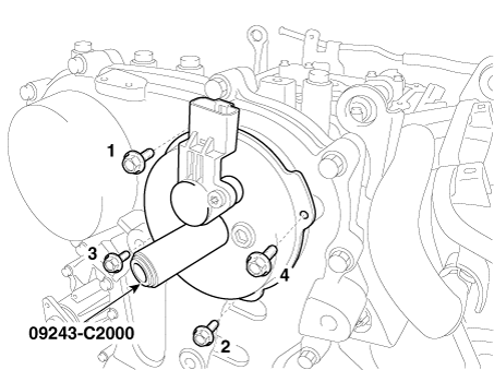
Insert the SST (09243-C2000) into the E-CVVT engine shaft.
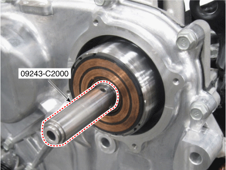
Slowly press the E-CVVT cover (A) until it is flush with the timing chain cover surface.
Pre-tighten the bolts in the sequence shown below, then remove the SST (09243-C2000).
Tightening torque: 1.0 - 2 N·m
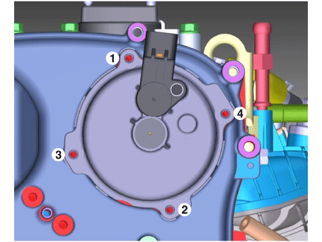
Tighten the bolts to the specified torque in the sequence shown below.
Tightening Torque: 9.8–11.8 N·m
Install the E-CVVT plug.
Using the SST (09243-C2000), insert the plug (A) into the E-CVVT cover hole.
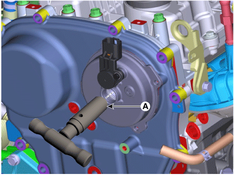
Install the SST stopper so that it is located at the end of the E-CVVT engine shaft.
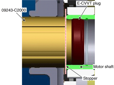
Check the press-in depth of the E-CVVT plug.
Using a steel rule, measure the distance from the E-CVVT cover boss center to the end of the engine shaft (①).
Using a steel rule, measure the distance from the E-CVVT cover center boss to the end of the E-CVVT plug (②).
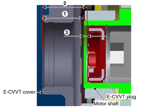
Calculate the press-in depth (③) of the engine plunger.
If it does not meet the specification, replace the E-CVVT plug with a new one and reinstall it.
Press-in depth: ③ = ② - ① Specification: 1.9–2.1 mm (0.0748–0.0827 in.)
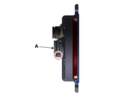
Install the E-CVVT cover plug so that the protrusion (A) correctly engages the E-CVVT cover groove.
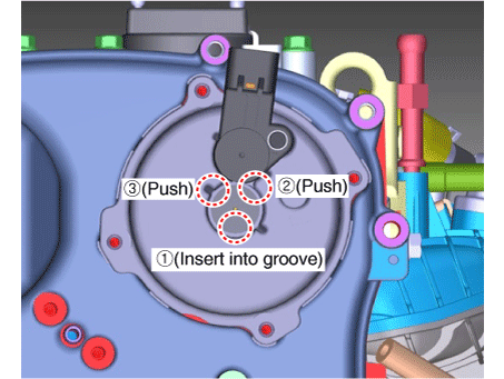
Install the remaining parts in the reverse order of removal.
Test yourself
A quick Kia Stinger CK quiz: every answer comes with an explanation and a link to the manual page.