Body Electrical System
Overhead Console Lamp
In this manual: Body Electrical System
6steps
~36min
2/5difficulty
Done 0 of 6
Circuit Diagrams
Connector and Terminal Function
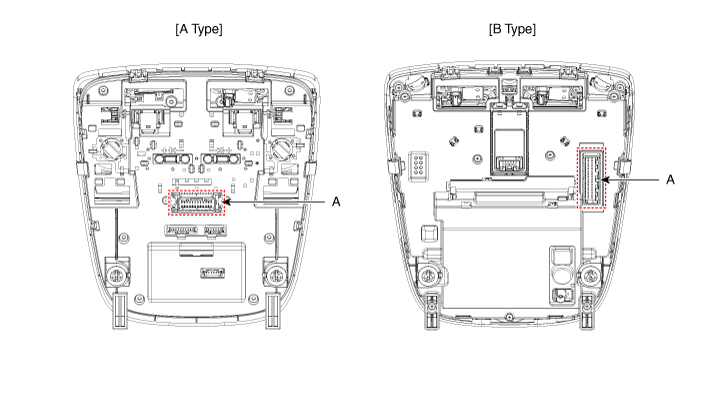
[Type]
| Connector A | ||
 |
||
| Pin | Except Russia Region | Russia only |
| Function | Function | |
| 1 | Battery (+) | Battery (+) |
| 2 | IGN1 (PAB) | - |
| 3 | IGN1 (SBR) | - |
| 4 | eCall PWM | - |
| 5 | - | - |
| 6 | eCall Button | eCall Button |
| 7 | - | - |
| 8 | eCall Ground | eCall Ground |
| 9 | Ground (Room, Door Lamp) | Ground (Room, Door Lamp) |
| 10 | PAB ON | - |
| 11 | PAB OFF | - |
| 12 | Ground (PAB, SBR) | - |
| 13 | LED (Red) | LED (Red) |
| 14 | LED (Green) | LED (Green) |
| 15 | ACC | - |
| 16 | Lower Rear Light | Lower Rear Light |
| 17 | - | - |
| 18 | Door (-) | Door (-) |
| 19 | Interior Lamp Signal | Interior Lamp Signal |
| 20 | SBR (Rear Left) | - |
| 21 | SBR (Rear Center) | - |
| 22 | SBR (Rear Right) | - |
| 23 | Ground (MCU eCall) | - |
| 24 | Ground (eCall LED) | Ground (eCall LED) |
[Type B]
| Connector A | ||
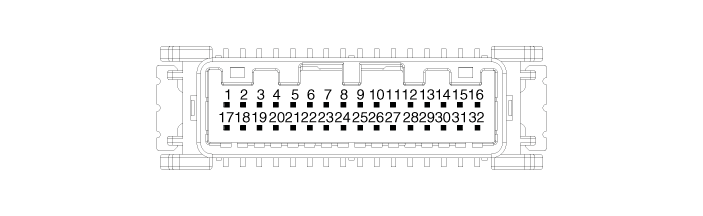 |
||
| Pin | Except Russia Region | Russia only |
| Function | Function | |
| 1 | Battery (+) | Battery (+) |
| 2 | IGN1 (PAB) | IGN1 (PAB) |
| 3 | - | - |
| 4 | eCall PWM | - |
| 5 | - | - |
| 6 | eCall Button | eCall Button |
| 7 | - | - |
| 8 | IGN1 (ETCS) | IGN1 (ETCS) |
| 9 | Ground (PAB, SBR, TMU) | Ground (PAB, SBR, TMU) |
| 10 | - | - |
| 11 | - | - |
| 12 | eCall Ground | eCall Ground |
| 13 | Ground (Room, Door Lamp) | Ground (Room, Door Lamp) |
| 14 | PAB ON | PAB ON |
| 15 | PAB OFF | PAB OFF |
| 16 | Door (-) | Door (-) |
| 17 | LED (Red) | LED (Red) |
| 18 | LED (Green) | LED (Green) |
| 19 | ACC | - |
| 20 | Lower Rear Light | Lower Rear Light |
| 21 | IGN1 (SBR) | IGN1 (SBR) |
| 22 | Interior Lamp Signal | Interior Lamp Signal |
| 23 | - | - |
| 24 | - | - |
| 25 | SBR (Rear Left) | SBR (Rear Left) |
| 26 | SBR (Rear Center) | SBR (Rear Center) |
| 27 | SBR (Rear Right) | SBR (Rear Right) |
| 28 | Ground (MCU eCall) | Ground (MCU eCall) |
| 29 | Ground (eCall LED) | Ground (eCall LED) |
| 30 | - | - |
| 31 | - | - |
| 32 | - | - |
Repair Procedures
Inspection
Remove the overhead console lamp.
(Refer to Lighting System - "Overhead Console Lamp")
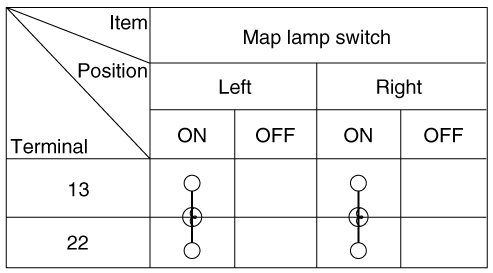
Check the circuit between the terminals for continuity.
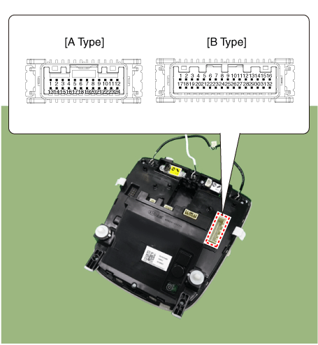
[Type]
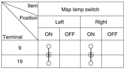
[Type B]
Removal
Disconnect the negative battery cable.
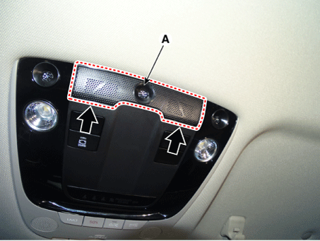
Remove the overhead console lamp microphone grille (A) using a flat-blade screwdriver or a remover tool.
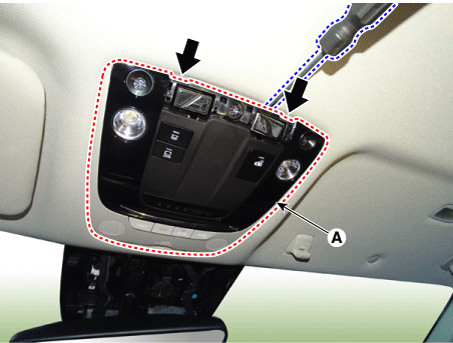
Remove the overhead console lamp (A) using a flat-blade screwdriver or a remover tool.
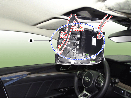
Disconnect all connectors (A) from the overhead lamp.
Installation
Install in the reverse order of removal.
Test yourself
A quick Kia Optima DL3 quiz: every answer comes with an explanation and a link to the manual page.
Was this page helpful?