Engine management
CONTROL UNIT
The control unit is located in the engine compartment, upper right on the front panel (Fig.13).
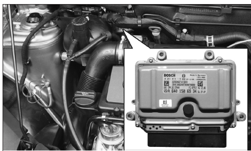
Control unit location. Fig. 13
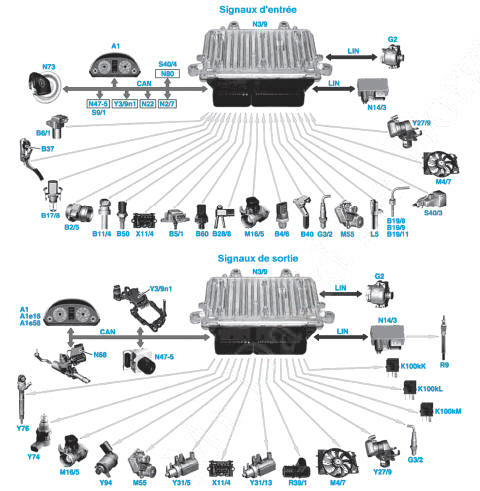
Fig. 14
Control unit input and output signals
A1. Instrument cluster
A1e16. Glow plug indicator lamp
A1e58. Engine diagnostic indicator lamp
B2/5. Hot-film mass air flow sensor
B4/6. Fuel pressure sensor
B5/1. Boost pressure sensor
B6/1. Camshaft sensor
B11/4. Coolant temperature sensor
B17/8. Charge air temperature sensor
B19/8. Exhaust gas temperature sensor after catalytic converter (with particulate filter)
B19/9. Exhaust gas temperature sensor before particulate filter
B19/11. Exhaust gas temperature sensor before turbocharger (with particulate filter)
B28/8. Differential pressure sensor (with particulate filter)
B37. Accelerator pedal sensors
B40. Oil sensor (oil level, temperature and quality)
B50. Fuel temperature sensor
B60. Exhaust back pressure sensor (with particulate filter)
G2. Alternator
G3/2. Lambda sensor
K100kK. Fuel pump relay
K100kL. Engine relay
K100kM. Starter relay
L5. Crankshaft sensor
M4/7. Engine cooling fan motor
M16/5. Throttle actuator (with particulate filter)
M55. Intake manifold switching motor
N2/7. Restraint systems control unit (airbags and belt tensioners)
N3/9. Engine control unit
N14/3. Glow plug final stage (glow plug pre/post-heating power relay)
N22. KLA control unit and keypad (automatic air conditioning)
N47-5. ESP and BAS control unit (brake assist)
N68. Electric power steering control unit
N73. EZS control unit (electronic ignition-starter switch)
N80. Steering column module
R9. Glow plugs
R39/1. Cylinder block ventilation heating element
S9/1. Brake light switch
S40/3. Clutch pedal switch (if gearbox 716)
S40/4. Tempomat (cruise control) button switch
X11/4. Diagnostic socket
Y3/9n1. CVT control unit (if gearbox 722.8)
Y27/9. Exhaust gas recirculation valve actuator (with particulate filter)
Y31/5. Boost pressure control solenoid valve
Y31/13. Throttle / EGR solenoid valve (without particulate filter)
Y74. Fuel pressure control solenoid valve
Y76. Injectors
Y94. Fuel flow control solenoid valve
CAN. Data bus (Controller Area Network)
LIN. Local data bus (Local Interconnected Network).
The CDI control unit controls, monitors and coordinates all engine management. To do this, it exchanges data with the other control units in the vehicle, which are networked together via the CAN (Controller Area Network) data bus.
Based on the incoming signals (Fig.14), the CDI control unit mainly manages the following systems:
- fuel injection,
- boost pressure control,
- exhaust gas recirculation,
- electronic accelerator pedal / cruise control,
- immobiliser,
- engine cooling,
- diesel particulate filter (optional),
- fault diagnosis.
Control unit pin assignment (Fig.15)
| Pins | Assignments |
Connector M |
|
| 1 | Injector 1 control |
| 2 | Injector 4 control |
| 6 | Lambda sensor (current measurement) |
| 8 | Exhaust back pressure sensor ground * / differential pressure sensor * |
| 10 | Hot-film mass air flow sensor ground / camshaft sensor |
| 12 | Engine block heater element control |
| 15 | Camshaft sensor supply |
| 20 | Intake manifold flap motor control |
| 22 | Boost pressure control solenoid valve control |
| 23 | Fuel pressure control solenoid valve supply |
| 25 | Injector 3 control |
| 26 | Injector 2 control |
| 31 | Lambda sensor (Nernst voltage) |
| 33 | Camshaft sensor signal |
| 34 | Oil sensor signal (oil level, temperature and quality) |
| 36 | Oil sensor ground (oil level, temperature and quality) |
| 41 | Boost pressure sensor / differential pressure sensor * / exhaust back pressure sensor * supply |
| 42 | Fuel pressure sensor supply |
| 44 | Oil sensor supply (oil level, temperature and quality) |
| 45 | Throttle actuator control * |
| 47 | Fuel flow control solenoid valve supply |
| 48 | Lambda sensor heater |
| 49 | Injector 2 ground |
| 50 | Injector 1 ground |
| 53 | Crankshaft position sensor signal |
| 56 | Fuel temperature sensor / coolant temperature sensor / boost air temperature sensor / pre-turbocharger gas temperature sensor * ground |
| 57 | Lambda sensor (ground) |
| 58 | Exhaust gas temperature sensor 2 * signal |
| 60 | Coolant temperature sensor signal |
| 61 | Fuel temperature sensor signal |
| 62 | Exhaust gas temperature sensor 1 * ground |
| 63 | Exhaust gas temperature sensor 2 * ground |
| 64 | Fuel pressure sensor ground |
| 65 | Fuel pressure sensor signal |
| 71 | Without particulate filter: EGR / throttle solenoid valve control |
| With particulate filter: EGR actuator control | |
| 73 | Injector 4 ground |
| 75 | Injector 3 ground |
| 77 | Crankshaft position sensor signal |
| 80 | Lambda sensor (pumping current) |
| 81 | Exhaust back pressure sensor * signal |
| 82 | Boost pressure sensor signal |
| 83 | Exhaust gas temperature sensor 1 * signal |
| 84 | Boost air temperature sensor signal |
| 86 | Hot-film air mass meter signal |
| 87 | Boost pressure sensor ground |
| 88 | Alternator control / glow plug pre/post-heating output stage control |
| 89 | Pre-turbocharger gas temperature sensor * signal |
| 90 | Differential pressure sensor * signal |
| 93 | Fuel pressure control solenoid valve ground |
| 94 | Fuel flow control solenoid valve ground |
| Unused pins: 3 to 5, 7, 9, 11, 13, 14, 16 to 19, 21, 24, 27 to 30, 32, 35, 37 to 40, 43, 46, 51, 52, 54, 55, 59, 66 to 70, 72, 74, 76, 78, 79, 85, 91, 92, 95 and 96. | |
| F connector | |
| 1 | Supply via engine relay through fuses 11 and 43 |
| 2 | Ground |
| 3 | Supply via engine relay through fuses 11 and 44 |
| 4 | Ground |
| 5 | Supply via engine relay through fuses 11 and 45 |
| 6 | Ground |
| 7 | Accelerator pedal sensor 1 ground |
| 12 | Accelerator pedal sensor 1 signal |
| 15 | Accelerator pedal sensors supply |
| 18 | Engine speed signal (to diagnostic socket) (until 05/2005) |
| 24 | Accelerator pedal sensor 2 signal |
| 32 | Fuel pump relay control |
| 34 | Clutch pedal switch signal (manual gearbox only) |
| 40 | Accelerator pedal sensor 2 ground |
| 41 | Ignition-switched supply via SAM control unit (cabin relay box) |
| 42 | Engine relay control |
| 44 | Starter relay control |
| 48 | Crash signal from restraint systems control unit (from 06/2006) |
| 51 | Engine CAN data bus High line |
| 52 | Engine CAN data bus Low line |
| 58 | Engine cooling fan motor control |
| Unused pins: 8 to 11, 13, 14, 16, 17, 19 to 23, 25 to 31, 33, 35 to 39, 43, 45 to 47, 49, 50, 53 to 57. | |
* only with DPF.
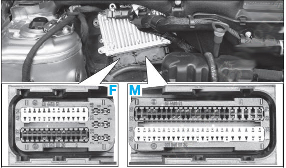
Engine control unit connector pin assignment Fig. 15
F. 58-pin connector
M. 96-pin connector.
COOLANT TEMPERATURE SENSOR
The coolant temperature sensor, NTC type, is located at the rear left of the cylinder head.
Resistance between pins M56 and M60:
- à 20 'C : 3 090 Ω,
- à 27 'C : 2 290 Ω,
- à 80 'C : 320 Ω.
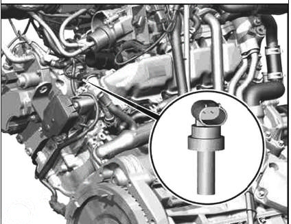
Coolant temperature sensor
BOOST AIR TEMPERATURE SENSOR
The boost air temperature sensor, NTC type, is located downstream of the throttle valve.
Resistance between pins M56 and M84 (at 27 °C): 4,630 Ω.
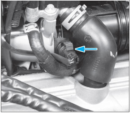
Boost air temperature sensor
PRE-TURBOCHARGER GAS TEMPERATURE SENSOR (WITH PARTICULATE FILTER)
The exhaust gas temperature sensor, PT200 type (platinum element), is located upstream of the turbocharger, at the exhaust manifold outlet.
Resistance between pins M56 and M89 (at 0 °C): 200 Ω.
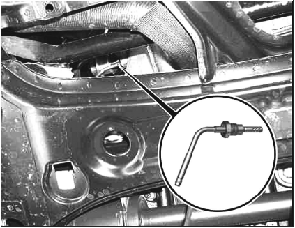
Pre-turbocharger exhaust gas temperature sensor (with particulate filter)
POST-CATALYTIC CONVERTER EXHAUST GAS TEMPERATURE SENSOR (WITH PARTICULATE FILTER)
The exhaust gas temperature sensor, PT200 type (platinum element), is located in the exhaust pipe behind the catalytic converter.
Resistance between terminals M58 and M63 (at 0 °C): 200 Ω.
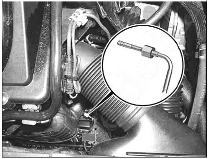
Post-catalytic converter exhaust gas temperature sensor (with particulate filter)
PRE-PARTICULATE FILTER EXHAUST GAS TEMPERATURE SENSOR
The exhaust gas temperature sensor, PT200 type (platinum element), is located in the exhaust pipe in front of the particulate filter.
Resistance between terminals M62 and M83 (at 0 °C): 200 Ω.
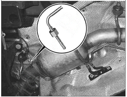
Pre-particulate filter exhaust gas temperature sensor
HOT-FILM MASS AIR FLOW SENSOR
The hot-film mass air flow sensor is located at the inlet of the air intake duct.
Resistance (at 20 °C):
- between terminals F3 and M86: 1.5 MΩ,
- between terminals F3 and M10: 209 kΩ,
- between terminals M10 and M86: 399 kΩ.
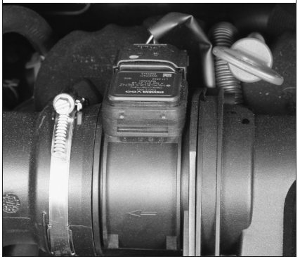
Hot-film mass air flow sensor
DIFFERENTIAL PRESSURE SENSOR (WITH PARTICULATE FILTER)
The differential pressure sensor, piezoresistive type, is located on the right side of the particulate filter, on the underbody of the vehicle.
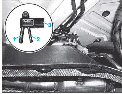
Differential pressure sensor (with particulate filter)
OIL SENSOR
The oil sensor is located on the top of the engine oil sump.
The oil level and oil quality are detected via the capacitance of the engine oil (dielectric properties).
The oil temperature is detected by an NTC-type sensor.
Resistance (at 20 °C):
between terminals M34 and M36: 360.5 kΩ,
between terminals M34 and M44: 1.5 MΩ,
between terminals M44 and M36: 1.4 MΩ.
BOOST PRESSURE SENSOR
The boost pressure sensor, potentiometer type, is located on the charge air pipe, downstream of the throttle.
Resistance (at 20 °C):
between terminals M41 and M87: 2.1 kΩ,
between terminals M41 and M82: 1.3 kΩ,
between terminals M82 and M87: 1.3 kΩ.
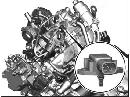
Boost pressure sensor
CAMSHAFT SENSOR
The camshaft sensor, Hall effect type, is located on the cylinder head.
Resistance (at 27 °C):
between terminals M10 and M15: 852 kΩ,
between terminals M10 and M33: 351 kΩ,
- between terminals M33 and M15: 1.3 MΩ.
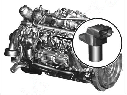
Camshaft sensor
EXHAUST GAS BACK PRESSURE SENSOR (WITH PARTICULATE FILTER)
The exhaust gas back pressure sensor, potentiometer type, is located on the exhaust gas recirculation (EGR) line, upstream of the EGR valve.
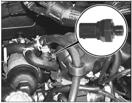
Exhaust gas back pressure sensor (with particulate filter)
LAMBDA SENSOR
The lambda sensor, wide-band type, is located at the inlet of the catalytic converter.
Resistance (at 27 °C):
between terminals F3 and M48: 3.5 Ω,
between terminals M80 and M6: 94 Ω,
between terminals M80 and M31: ∞,
between terminals M80 and M57: ∞,
between terminals M6 and M31: ∞,
between terminals M6 and M57: ∞,
between terminals M57 and M31: ∞.
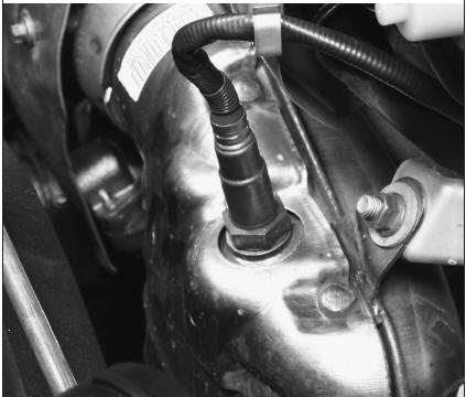
Lambda sensor
CRANKSHAFT SENSOR
The crankshaft position sensor, inductive type, is located at the front left of the engine block.
Resistance between terminals M53 and M77 (at 27 °C): 1.1 kΩ.
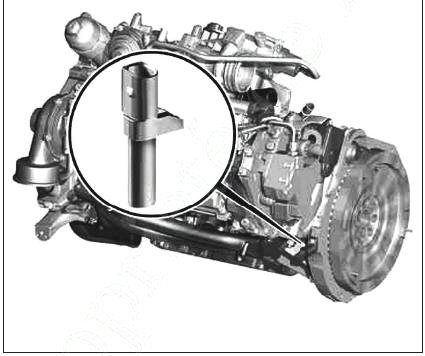
Crankshaft sensor
THROTTLE / EGR SOLENOID VALVE (WITHOUT PARTICULATE FILTER)
The throttle / EGR solenoid valve (called the pressure converter) is located at the front left of the engine, on the air filter housing.
The throttle / EGR solenoid valve controls the vacuum capsule for throttling the intake air and, at the same time, the vacuum capsule for opening the exhaust gas recirculation (EGR).
Resistance between terminals F3 and M71 (at 27 °C): 16.2 Ω.
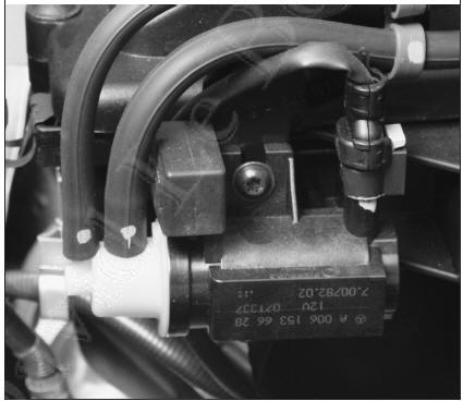
Throttle / EGR solenoid valve (without particulate filter)
THROTTLE ACTUATOR (WITH PARTICULATE FILTER)
The throttle actuator is located on the intake line, above the cylinder head.
The throttle actuator regulates (restricts) the amount of fresh air directed to the engine during exhaust gas recirculation.
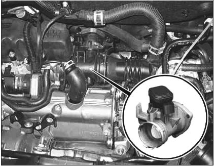
Throttle actuator (with particulate filter)
EGR VALVE ACTUATOR (WITH PARTICULATE FILTER)
The EGR valve actuator is located on the intake line, above the cylinder head.
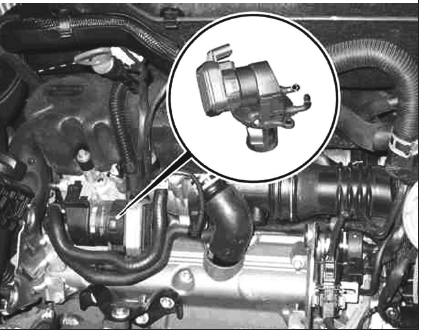
EGR valve actuator (with particulate filter)
INTAKE RUNNER CONTROL MOTOR
The intake runner control motor is located on the left side, on the intake runner control housing.
The charge air distributor has, for each cylinder, a filling intake duct and a swirl intake duct.
In the lower engine speed and load range, the filling intake ducts are closed by the flaps. The entire air mass flows exclusively through the swirl intake ducts. The resulting strong air swirl improves the mixing of fuel with air. This improves combustion, which allows a higher engine torque to be obtained and reduces soot particles in the exhaust gas. As engine speed and load increase, the filling intake ducts open progressively, so that in every operating phase the best possible air swirl is achieved and the required air mass is available. This optimizes the exhaust gas emission characteristics as well as engine torque.
Resistance (at 27 °C):
between terminals F3 and M20: 1.4 kΩ,
between terminals M20 and ground: 8.4 kΩ.
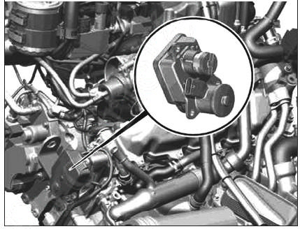
Intake runner control motor
GLOW TIME OUTPUT STAGE
The glow time output stage (glow plug supply relay) is located on the left side of the engine, behind the air filter housing.
Resistance between terminals F3 and M88, at 27 °C: 471.3 kΩ.
Resistance of the disconnected component (at 27 °C):
between terminals 1 and 2: ∞,
between pins 1 and 3: ∞,
between pins 2 and 3: 20 kΩ,
between pins 5 and 6: 27.5 kΩ,
between pins 5 and 7: 27.5 kΩ,
between pins 5 and 8: 27.5 kΩ.
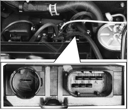
Glow time output stage
GLOW PLUGS
The glow plugs are located behind the cylinder head.
The glow plugs are supplied by the glow time output stage with a voltage of 6 to 11 V.
Resistance (at 27 °C): 0.6 Ω.
CRANKCASE BREATHER HEATING ELEMENT
The crankcase breather heating element is located on the crankcase breather pipe.
It prevents the crankcase breather pipe from clogging due to condensation water freezing or heavy components of the engine oil.
Resistance between pins F3 and M12 (at 27 °C): 12.4 Ω.
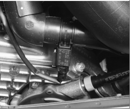
Crankcase breather heating element
ACCELERATOR PEDAL SENSORS
The two accelerator pedal sensors, Hall-effect type, are mounted on the accelerator pedal bracket.
Resistance (at 27 °C) (pedal released):
between pins F15 and F12: 133.1 Ω,
between pins F15 and F40: 260.6 Ω,
between pins F15 and F7: 271.4 Ω,
between pins F15 and F24: 137.3 Ω,
between pins F12 and F40: 131.1 Ω,
between pins F7 and F24: 128.2 Ω.
BOOST PRESSURE CONTROL SOLENOID VALVE
The boost pressure control solenoid valve (called pressure converter) is located behind the air filter housing.
Resistance between pins M22 and F3 (at 20 °C): 16.1 Ω.
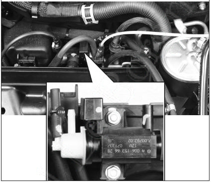
Boost pressure control solenoid valve
Test yourself
A quick Mercedes-Benz B-Class quiz: every answer comes with an explanation and a link to the manual page.