A/t Fluid Cooler
Exploded View
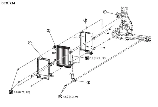
 |
Bracket |  |
A/T fluid cooler air guide RR |  |
A/T fluid cooler |
 |
A/T fluid cooler air guide FR |  |
Bracket | ||
 |
: N·m (kg-m, ft-lb) | ||||
 |
: N·m (kg-m, in-lb) | ||||
Removal and Installation
REMOVAL
Remove Front bumper. Refer to Exploded View.
Remove clip ( ) and remove A/T fluid cooler air guide FR
 from A/T fluid cooler.
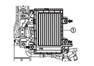
Remove A/T fluid cooler hose A from the A/T fluid cooler using the following procedure:
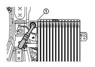
Remove A/T fluid cooler hose cap
from A/T fluid cooler hose A  .
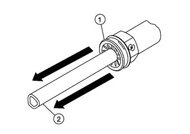
Install suitable disconnect tool (A) (commercial service tool) on to the A/T fluid cooler hose A at the A/T fluid cooler side.

Rotate suitable disconnect tool (A) (commercial service tool) counter clockwise 60 degrees to release snap ring.
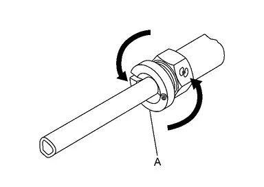
Remove A/T fluid cooler hose A
from the A/T fluid cooler.
Remove A/T fluid cooler hose B from A/T fluid cooler using the following procedure:

Remove A/T fluid cooler hose cap
from A/T fluid cooler hose B .Install suitable disconnect tool (A) (commercial service tool) on to the A/T fluid cooler hose B at the A/T fluid cooler side.
Rotate suitable disconnect tool (A) (commercial service tool) counter clockwise 60 degrees to release snap ring.
Remove A/T fluid cooler hose B
from the A/T fluid cooler.Remove clip (
) from A/T fluid cooler.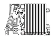
Remove A/T fluid cooler mount bolt (
) and remove A/T fluid cooler .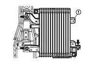
Remove clip (
) and remove A/T fluid cooler air guide RR from A/T fluid cooler.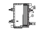
Remove bracket mounting bolt (
) and remove bracket .
INSTALLATION
Installation is in the reverse order of removal.
Inspection and Adjustment
INSPECTION AFTER INSTALLATION
Check for A/T fluid leakage. Refer to Inspecton.
ADJUSTMENT AFTER INSTALLATION
Adjust A/T fluid level. Refer to Adjustment.