Transmission Assembly
2wd
Exploded View

 |
Bracket |  |
A/T assembly |  |
Bracket |
 |
Bracket | ||||
 |
: N·m (kg-m, ft-lb) |
Removal and Installation
REMOVAL
Release the parking brake.
Activate the neutral hold mode. Refer to Neutral Hold Mode Indicator.
Ignition switch OFF.
Disconnect the battery cable from the negative terminal.
Remove front under cover. Refer to Removal and Installation.
Remove starter motor. Refer to Removal and Installation.
Drain engine coolant. Refer to ENGINE COOLANT : Draining.
Drain A/T fluid. Refer to Draining.
Remove water hoses from the A/T fluid warmer. Refer to Removal and Installation.
Remove A/T fluid warmer. Refer to Removal and Installation.
Remove A/T fluid cooler tubes from the A/T assembly. Refer to Removal and Installation.
Plug up openings such as the A/T fluid cooler tube holes.
Remove A/T air breather hose from the A/T assembly. Refer to Removal and Installation.
Remove heat shield mounting bolts and remove the heat shield. Refer to Removal and Installation.
Disconnect harness connector from control valve & TCM. Refer to Removal and Installation.
Remove exhaust muffler. Refer to EXHAUST SYSTEM : Removal & Installation.
Remove rear propeller shaft. Refer to Removal and Installation.
Disconnect heated oxygen sensor harness connector and remove bracket. Refer to Removal and Installation.
Remove catalyst converter support bracket. Refer to Removal and Installation.
Remove Catalyst converter (bank 2). Refer to Removal and Installation.
Remove crankshaft position sensor. Refer to Removal and Installation.
Remove rear plate cover. Refer to Exploded View.
Turn crankshaft, and remove the four tightening bolts ( ) for drive plate and torque converter.
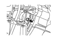
Using a suitable jack and Transmission jack adaptor (SST: NI–52940) (A), support the transmission assembly  .


Remove rear engine mounting cross member. Refer to Unit Removal & Installation.
Remove bolts  fixing A/T assembly to engine.
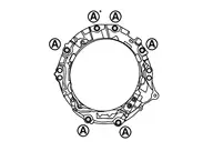
*: Tightening the bolt with bracket. Refer to Exploded View.
Remove A/T assembly from the vehicle.
INSTALLATION
Note the followings and Install in the reverse order of removal.
Check fitting of dowel pins (
 ).
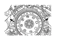
Align the positions of tightening bolts for drive plate with those of the torque converter, and temporarily tighten the bolts (
). Then, tighten the bolts with the specified torque.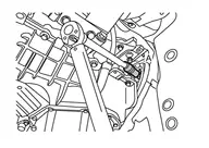
Inspection and Adjustment
INSPECTION BEFORE INSTALLATION
Be sure to check dimension (A) to ensure it is within the reference value limit.

| B | : Scale |
| C | : Straightedge |
| Dimension (A) | : Refer to Torque Converter. |
INSPECTION AFTER INSTALLATION
Start the engine and check visually that there is no leakage of ATF.
Check A/T position. Refer to Inspection.
ADJUSTMENT AFTER INSTALLATION
Adjust A/T fluid level. Refer to Adjustment.
When replaced A/T assembly, perform "ADDITIONAL SERVICE WHEN REPLACING TRANSMISSION ASSEMBLY". Refer to Description.
4wd
Exploded View
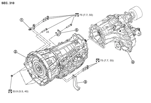
|
Bracket | |
A/T assembly | |
Bracket |
|
Transfer assembly |  |
Bracket | ||
|
: N·m (kg-m, ft-lb) |
Removal and Installation
REMOVAL
Release the parking brake.
Activate the neutral hold mode. Refer to Neutral Hold Mode Indicator.
Ignition switch OFF.
Disconnect the battery cable from the negative terminal.
Remove front under cover. Refer to Removal and Installation.
Remove starter motor. Refer to Removal and Installation.
Drain engine coolant. Refer to ENGINE COOLANT : Draining.
Drain A/T fluid. Refer to Draining.
Remove water hoses from the A/T fluid warmer. Refer to Removal and Installation.
Remove A/T fluid warmer. Refer to Removal and Installation.
Remove A/T fluid cooler tubes from the A/T assembly. Refer to Removal and Installation.
Plug up openings such as the A/T fluid cooler tube holes.
Disconnect harness connector from transfer range position sensor.
Without "4L" switch (on 4WD shift switch) and differential lock system: Refer to Removal and Installation (Transfer: ATX93A).
With "4L" switch (on 4WD shift switch) and without differential lock system: Refer to Removal and Installation (Transfer: ATX93B).
With "4L" switch (on 4WD shift switch) and differential lock system: Refer to Removal and Installation (Transfer: ATX93C).
Remove A/T air breather hose from the A/T assembly. Refer to Removal and Installation.
Remove heat shield mounting bolts and remove the heat shield. Refer to Removal and Installation.
Disconnect harness connector from control valve & TCM. Refer to Removal and Installation.
Disconnect harness connector from transfer control actuator.
Without "4L" switch (on 4WD shift switch) and differential lock system: Refer to Removal and Installation (Transfer: ATX93A).
With "4L" switch (on 4WD shift switch) and without differential lock system: Refer to Removal and Installation (Transfer: ATX93B).
With "4L" switch (on 4WD shift switch) and differential lock system: Refer to Removal and Installation (Transfer: ATX93C).
Remove main muffler. Refer to EXHAUST SYSTEM : Removal & Installation.
Remove rear propeller shaft. Refer to Removal and Installation.
Remove front final drive assembly. Refer to Removal and Installation.
Disconnect heated oxygen sensor harness connector and remove bracket. Refer to Removal and Installation.
Remove catalyst converter support bracket. Refer to Removal and Installation.
Remove Catalyst converter (bank 2). Refer to Removal and Installation.
Remove crankshaft position sensor. Refer to Removal and Installation.
Remove rear plate cover. Refer to Exploded View.
Turn crankshaft, and remove the four tightening bolts () for drive plate and torque converter.
Using a suitable jack and Transmission jack adaptor (SST: NI–52940) (A), support the transmission assembly .
Support the transfer assembly with transmission jack.
Remove rear engine mounting cross member. Refer to Unit Removal & Installation.
Remove bolts fixing A/T assembly to engine.
*: Tightening the bolt with bracket. Refer to Exploded View.
Remove A/T assembly with transfer assembly from the vehicle.
Remove transfer assembly from transmission assembly.
Without "4L" switch (on 4WD shift switch) and differential lock system: Refer to Removal and Installation (Transfer: ATX93A).
With "4L" switch (on 4WD shift switch) and without differential lock system: Refer to Removal and Installation (Transfer: ATX93B).
With "4L" switch (on 4WD shift switch) and differential lock system: Refer to Removal and Installation (Transfer: ATX93C).
INSTALLATION
Note the followings and Install in the reverse order of removal.
Check fitting of dowel pins (
).Align the positions of tightening bolts for drive plate with those of the torque converter, and temporarily tighten the bolts (
). Then, tighten the bolts with the specified torque.
Inspection and Adjustment
INSPECTION BEFORE INSTALLATION
Be sure to check dimension (A) to ensure it is within the reference value limit.
| B | : Scale |
| C | : Straightedge |
| Dimension (A) | : Refer to Torque Converter. |
INSPECTION AFTER INSTALLATION
Start the engine and check visually that there is no leakage of ATF.
Check A/T position. Refer to Inspection.
ADJUSTMENT AFTER INSTALLATION
Adjust A/T fluid level. Refer to Adjustment.
When replaced A/T assembly, perform "ADDITIONAL SERVICE WHEN REPLACING TRANSMISSION ASSEMBLY". Refer to Description.