Water Hose
Exploded View
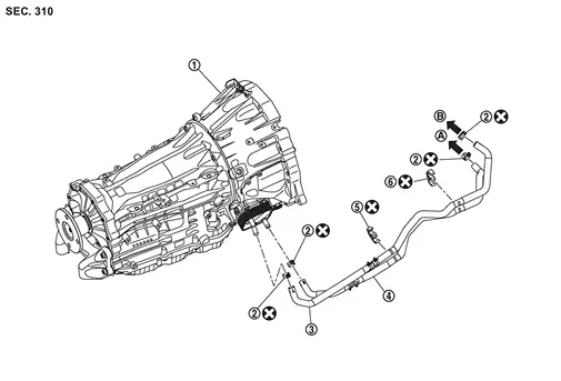
 |
A/T assembly |  |
Hose clamp |  |
A/T water hose A |
 |
A/T water hose B |  |
Clip A |  |
Clip B |
 |
To water pipe. Refer to Exploded View. |  |
To oil cooling exchanger. Refer to Exploded View. | ||
 |
: Always replace after every disassembly. | ||||
Removal and Installation
REMOVAL
Remove front under cover. Refer to Removal and Installation.
Drain engine coolant. Refer to ENGINE COOLANT : Draining.
Remove hose clamps  , and remove A/T water hose A
 and A/T water hose B from A/T fluid warmer.

Remove A/T water hose A and A/T water hose B from clip A .
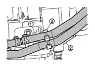
Remove A/T water hose A and A/T water hose B from clip B .
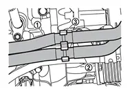
Remove hose clamp , and remove A/T water hose A from water pipe.
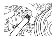
Remove hose clamp , and remove A/T water hose B from oil cooling exchanger.
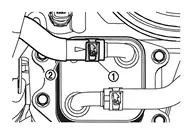
Remove clip A and clip B from bracket.
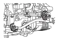
INSTALLATION
Note the following, and install in the reverse order of removal.
Refer to the following when installing A/T water hose.
Water hose Installation side tube Direction of paint mark Hose insertion depth (L) A/T Water hose A Water pipe Align with the paint mark on water pipe End reaches the 2-stage bulge. A/T fluid warmer Align with the paint mark on the A/T fluid warmer A/T Water hose B A/T fluid warmer Align with the paint mark on the A/T fluid warmer oil cooling exchanger Frontward 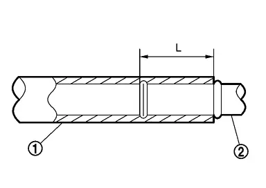
Refer to the following when installing hose clamps.
Water hose Installation side tube Hose clamp 
Direction of tab Clamping position Water hose A Water pipe Frontward 3 - 7 mm (0.12 - 0.28 in) (A) from hose end. A/T fluid warmer Upward Water hose B A/T fluid warmer Upward oil cooling exchanger Frontward 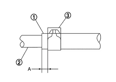
When installing the A/T water hose
to the clip , attach the paint mark on the A/T water hose to the rightward of the vehicle.
Inspection and Adjustment
INSPECTION AFTER INSTALLATION
Start the engine, and check the joints for coolant leakage. Refer to ENGINE COOLANT : Inspection.