Cooling fan
Component Function Check
1.CHECK COOLING FAN FUNCTION With CONSULT-III
1. Turn ignition switch ON. 2. Perform “FAN DUTY CONTROL” in “ACTIVE TEST” mode of “ENGINE” using CONSULT-III.
3. Check that cooling fan speed varies according to the percentage.
 Without CONSULT-III
1. Activate IPDM E/R auto active test and check cooling fan motors operation. Refer to PCS-12, "Diagnosis Description".
2. Check that cooling fan operates.
Is the inspection result normal? YES >> INSPECTION END
NO >> Proceed to EC-420, "Diagnosis Procedure".
Diagnosis Procedure
1.CHECK COOLING FAN CONTROL MODULE POWER SUPPLY 1. Turn ignition switch OFF. 2. Disconnect cooling fan control nodule harness connector. 3. Turn ignition switch ON.4. Check the voltage between cooling fan control nodule harness connector and ground.

Is the inspection result normal? YES >> GO TO 5.
NO >> GO TO 2.
2.CHECK COOLING FAN CONTROL MODULE POWER SUPPLY CIRCUIT 1. Turn ignition switch OFF. 2. Disconnect cooling fan relay harness connector.3. Check the continuity between cooling fan control nodule harness connector and cooling fan relay harness connector.
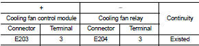
4. Also check harness for short to ground.
Is the inspection result normal? YES >> GO TO 3.
NO >> Repair or replace error-detected parts.
3.CHECK COOLING FAN RELAY POWER SUPPLY CIRCUIT 1. Disconnect IPDM E/R harness connector.2. Check the continuity between cooling fan relay harness connector and IPDM E/R harness connector.

3. Also check harness for short to ground.
Is the inspection result normal? YES >> GO TO 4.
NO >> Repair or replace error-detected parts.
4.CHECK COOLING FAN RELAYCheck cooling fan relay. Refer to EC-422, "Component Inspection (Cooling Fan Relay)".
Is the inspection result normal? YES >> Perform the trouble diagnosis for power supply circuit.
NO >> Replace cooling fan relay. Refer to PG-7, "Standardized Relay".
5.CHECK COOLING FAN CONTROL MODULE GROUND CIRCUIT 1. Turn ignition switch OFF.2. Check the continuity between cooling fan control nodule harness connector and ground.
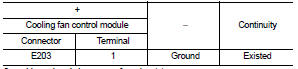
3. Also check harness for short to power.
Is the inspection result normal? YES >> GO TO 6.
NO >> Repair or replace error-detected parts.
6.CHECK COOLING FAN CONTROL SIGNAL CIRCUIT 1. Disconnect IPDM E/R harness connector.2. Check the continuity between cooling fan control nodule harness connector and IPDM E/R harness connector.
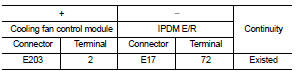
3. Also check harness for short to ground and to power.
Is the inspection result normal? YES >> GO TO 7.
NO >> Repair or replace error-detected parts.
7.CHECK COOLING FAN CONTROL MODULE OUTPUT SIGNAL CIRCUIT 1. Reconnect all harness connectors disconnected. 2. Disconnect cooling fan control module harness connector. 3. Turn ignition switch ON.4. Check the voltage between cooling fan control module terminals and ground.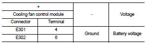
Is the inspection result normal? YES >> GO TO 8.
NO >> Repair or replace error-detected parts.
8.CHECK COOLING FAN MOTORS -1 AND -2Check the cooling fan motor. Refer to EC-422, "Component Inspection (Cooling Fan Motor)".
YES >> Check intermittent incident. Refer to GI-42, "Intermittent Incident".
NO >> Replace cooling motor. Refer to CO-20, "Exploded View".
Component Inspection (Cooling Fan Motor)
1.CHECK COOLING FAN MOTOR 1. Turn ignition switch OFF. 2. Disconnect cooling fan control module harness connector.3. Supply cooling fan control module harness connector terminals with battery voltage as per the following, and check operation.
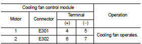
Is the inspection result normal? YES >> INSPECTION END
NO >> Replace malfunctioning cooling fan motor. Refer to CO-20, "Exploded View".
Component Inspection (Cooling Fan Relay)
1.CHECK COOLING FAN RELAY 1. Turn ignition switch OFF. 2. Remove cooling fan relay.3. Check the continuity between cooling fan relay terminals under the following conditions
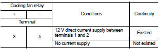
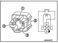
Is the inspection result normal? YES >> INSPECTION END
NO >> Replace cooling fan relay. Refer to PG-7, "Standardized Relay".