Power supply and ground circuit
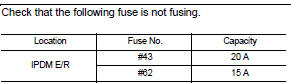
Is the fuse fusing? YES >> Replace the fuse after repairing the applicable circuit.
NO >> GO TO 2.
2.CHECK GROUND CONNECTION 1. Turn ignition switch OFF.2. Check ground connection E21 and E38. Refer to GI-44, "Circuit Inspection".
Is the inspection result normal? YES >> GO TO 3.
NO >> Repair or replace ground connection.
3.CHECK ECM GROUND CIRCUIT 1. Disconnect ECM harness connectors.2. Check the continuity between ECM harness connector and ground.
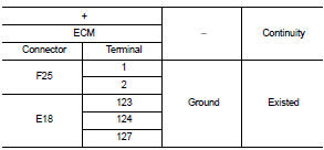
Is the inspection result normal? YES >> GO TO 4.
NO >> Repair or replace error-detected parts.
4.CHECK ECM POWER SUPPLY (MAIN)-I 1. Reconnect ECM harness connector. 2. Turn ignition switch ON.3. Check the voltage between ECM harness connector terminals.
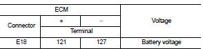
Is the inspection result normal? YES >> GO TO 5.
NO >> GO TO 6.
5.CHECK ECM POWER SUPPLY (MAIN)-II 1. Turn ignition switch OFF and wait at least 10 seconds.2. Check the voltage between ECM harness connector terminals as per the following.
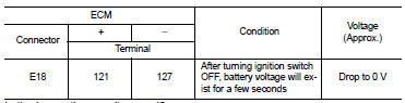
Is the inspection result normal? YES >> GO TO 9.
NO >> GO TO 7.
6.CHECK ECM POWER SUPPLY (MAIN) CIRCUIT 1. Turn ignition switch OFF. 2. Disconnect ECM harness connectors. 3. Disconnect IPDM E/R harness connector.4. Check the continuity between ECM harness connector and IPDM E/R harness connector.
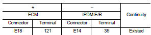
5. Also check harness for short to ground.
Is the inspection result normal? YES >> Perform the trouble diagnosis for power supply circuit.
NO >> Repair or replace error-detected parts.
7.CHECK ECM RELAY CONTROL SIGNALCheck the voltage between ECM harness connector terminals as per the following.
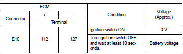
Is the inspection result normal? YES >> Check Intermittent Incident. Refer to GI-42, "Intermittent Incident".
NO >> GO TO 8.
8.CHECK ECM RELAY CONTROL SIGNAL CIRCUIT 1. Turn ignition switch OFF. 2. Disconnect ECM harness connector. 3. Disconnect IPDM E/R harness connector.4. Check the continuity between ECM harness connector and IPDM E/R harness connector.
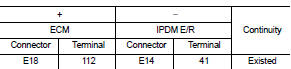
5. Also check harness for short to ground and to power.
Is the inspection result normal? YES >> Replace IPDM E/R. Refer to PCS-34, "Removal and Installation".
NO >> Repair or replace error-detected parts.
9.CHECK IGNITION SWITCH SIGNAL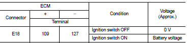
Is the inspection result normal? YES >> GO TO 11.
NO >> GO TO 10.
10.CHECK IGNITION SWITCH SIGNAL CIRCUIT 1. Turn ignition switch OFF. 2. Disconnect ECM harness connector. 3. Disconnect IPDM E/R harness connector.4. Check the continuity between ECM harness connector and IPDM E/R harness connector.

5. Also check harness for short to ground and to power.
Is the inspection result normal? YES >> Perform the trouble diagnosis for power supply circuit.
NO >> Repair or replace error-detected parts.
11.CHECK ECM POWER SUPPLY (BACK-UP)Check the voltage between ECM harness connector terminals.
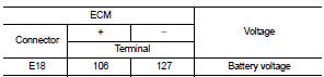
Is the inspection result normal? YES >> Check Intermittent Incident. Refer to GI-42, "Intermittent Incident".
NO >> GO TO 12.
12.CHECK ECM POWER SUPPLY (BACK-UP) CIRCUIT 1. Turn ignition switch OFF. 2. Disconnect ECM harness connector. 3. Disconnect IPDM E/R harness connector.4. Check the continuity between ECM harness connector and IPDM E/R harness connector.
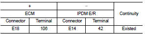
5. Also check harness for short to ground.
Is the inspection result normal? YES >> Perform the trouble diagnosis for power supply circuit.
NO >> Repair or replace error-detected parts.