Low pressure fuel pump
M/T models : Component Function Check
1.CHECK FUEL PUMP FUNCTION 1. Turn ignition switch ON.2. Pinch fuel feed hose with two fingers.
NOTE:
Fuel pressure pulsation should be felt on the fuel feed hose for 1 second after ignition switch is turned ON.
Is the inspection result normal? YES >> INSPECTION END
NO >> Proceed to EC-405, "M/T MODELS : Diagnosis Procedure".
M/T models : Diagnosis Procedure
1.CHECK FPCM POWER SUPPLY 1. Turn ignition switch OFF. 2. Disconnect FPCM harness connector. 3. Turn ignition switch ON.4. Check the voltage between FPCM harness connector and ground.
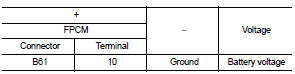
Is the inspection result normal? YES >> GO TO 2.
NO >> GO TO 3.
2.CHECK FPCM POWER SUPPLY CIRCUIT 1. Turn ignition switch OFF. 2. Disconnect IPDM E/R harness connector.3. Check the continuity between FPCM harness connector and IPDM E/R harness connector.

4. Also check harness for short to ground.
Is the inspection result normal? YES >> Perform the trouble diagnosis for power supply circuit.
NO >> Repair or replace error-detected parts.
3.CHECK FPCM GROUND CIRCUIT 1. Turn ignition switch OFF.2. Check the continuity between FPCM harness connector and ground.
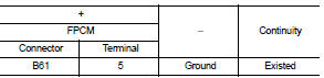
3. Also check harness for short to power.
Is the inspection result normal? YES >> GO TO 4.
NO >> Repair or replace error-detected parts.
4.CHECK FPCM INPUT AND OUTPUT CIRCUITS 1. Disconnect ECM harness connector.2. Check the continuity between FPCM harness connector and ECM harness connector.
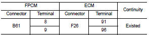
3. Also check harness for short to ground and to power.
Is the inspection result normal? YES >> GO TO 5.
NO >> Repair or replace error-detected parts.
5.CHECK FUEL PUMP CONTROL CIRCUIT 1. Disconnect fuel level sensor unit (fuel pump) harness connector.2. Check the continuity between FPCM harness connector and fuel level sensor unit (fuel pump) harness connector.

3. Also check harness for short to ground and to power.
Is the inspection result normal? YES >> GO TO 6.
NO >> Repair or replace error-detected parts.
6.CHECK LOW PRESSURE FUEL PUMPCheck the low pressure fuel pump. Refer to EC-406, "M/T MODELS : Component Inspection (Low Pressure Fuel Pump)".
Is the inspection result normal? YES >> Check intermittent incident .Refer to GI-42, "Intermittent Incident".
NO >> Replace fuel level sensor unit. Refer to FL-6, "2WD : Exploded View" (2WD) or FL-10, "4WD : Exploded View" (4WD).
7.CHECK FPCMCheck the FPCM. Refer to EC-407, "M/T MODELS : Component Inspection (FPCM)".
Is the inspection result normal? YES >> Check intermittent incident .Refer to GI-42, "Intermittent Incident".
NO >> Replace FPCM. Refer to EC-448, "Removal and Installation".
M/T models : Component Inspection (Low Pressure Fuel Pump)
1.CHECK FUEL PRESSURE REGULATOR 1. Turn ignition switch OFF.2. Check low fuel pressure. Refer to EC-140, "Work Procedure".
Is inspection result normal? YES >> INSPECTION END
NO >> GO TO 2.
2.CHECK LOW PRESSURE FUEL PUMP 1. Turn ignition switch OFF. 2. Disconnect fuel level sensor unit.3. Check resistance between fuel level sensor unit terminals as follows.
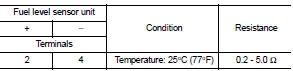
Is the inspection result normal? YES >> INSPECTION END
NO >> Replace fuel level sensor unit. Refer to FL-6, "2WD : Exploded View" (2WD) or FL-10, "4WD : Exploded View" (4WD).
M/T models : Component Inspection (FPCM)
1.CHECK FUEL PUMP CONTROL MODULE (FPCM)Check the voltage between FPCM terminals as per the following conditions.
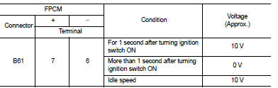
Is the inspection result normal? YES >> INSPECTION END
NO >> Replace FPCM. Refer to EC-448, "Removal and Installation".
Except for M/T models : Component Function Check
1.CHECK FUEL PUMP FUNCTION 1. Turn ignition switch ON.2. Pinch fuel feed hose with two fingers.
NOTE: Fuel pressure pulsation should be felt on the fuel feed hose for 1 second after ignition switch is turned ON.
Is the inspection result normal? YES >> INSPECTION END
NO >> Proceed to EC-405, "M/T MODELS : Diagnosis Procedure".
Except for m/t models : Diagnosis Procedure
1.CHECK FUEL PUMP RELAY POWER SUPPLY 1. Turn ignition switch OFF. 2. Disconnect ECM harness connector. 3. Turn ignition switch ON.4. Check the voltage between ECM harness connector terminals.
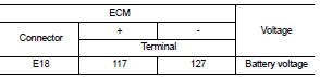
Is the inspection result normal? YES >> GO TO 3.
NO >> GO TO 2.
2.CHECK FUEL PUMP RELAY POWER SUPPLY CIRCUIT 1. Turn ignition switch OFF. 2. Disconnect IPDM E/R harness connector.3. Check the continuity between ECM harness connector and IPDM E/R harness connector.
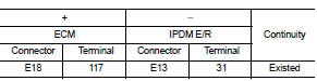
4. Also check harness for short to ground.
Is the inspection result normal? YES >> Perform the trouble diagnosis for power supply circuit.
NO >> Repair or replace error-detected parts.
3.CHECK LOW FUEL PUMP POWER SUPPLY 1. Turn ignition switch OFF. 2. Reconnect ECM harness connector. 3. Disconnect fuel level sensor unit harness connector. 4. Turn ignition switch ON.5. Check the voltage between fuel level sensor unit harness connector and ground.
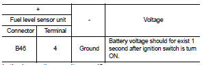
Is the inspection result normal? YES >> GO TO 5.
NO >> GO TO 4.
4.CHECK LOW FUEL PUMP POWER SUPPLY CIRCUIT 1. Turn ignition switch OFF. 2. Disconnect IPDM E/R harness connector.3. Check the continuity between fuel level sensor unit harness connector and IPDM E/R harness connector.

4. Also check harness for short to ground.
Is the inspection result normal? YES >> Perform the trouble diagnosis for power supply circuit.
NO >> Repair or replace error-detected parts.
5.CHECK LOW FUEL PUMP GROUND CIRCUIT 1. Turn ignition switch OFF.2. Check the continuity between fuel level sensor unit harness connector and ground.

3. Also check harness for short to power.
Is the inspection result normal? YES >> GO TO 6.
NO >> Repair or replace error-detected parts.
6.CHECK LOW FUEL PUMPCheck the low fuel pump. Refer to EC-409, "EXCEPT FOR M/T MODELS : Component Inspection (Low Pressure Fuel Pump)".
Is the inspection result normal? YES >> Check intermittent incident. Refer to GI-42, "Intermittent Incident".
NO >> Replace fuel level sensor unit. Refer to FL-6, "2WD : Exploded View" (2WD) or FL-10, "4WD : Exploded View" (4WD).
Except for m/t models : Component Inspection (Low Pressure Fuel Pump)
1.CHECK FUEL PRESSURE REGULATOR 1. Turn ignition switch OFF.2. Check low fuel pressure. Refer to EC-140, "Work Procedure".
Is inspection result normal? YES >> INSPECTION END
NO >> GO TO 2.
2.CHECK LOW PRESSURE FUEL PUMP 1. Turn ignition switch OFF. 2. Disconnect fuel level sensor unit.3. Check resistance between fuel level sensor unit terminals as follows.
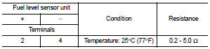
Is the inspection result normal? YES >> INSPECTION END
NO >> Replace fuel level sensor unit. Refer to FL-6, "2WD : Exploded View" (2WD) or FL-10, "4WD : Exploded View" (4WD).