P0234 TC system
DTC Logic
DTC DETECTION LOGIC
NOTE:
If DTC P0234 is displayed with DTC P0237 or P0238, first perform the trouble diagnosis for DTC P0237 or P0238. Refer to EC-260, "DTC Logic".

DTC CONFIRMATION PROCEDURE
1.PERFORM COMPONENT FUNCTION CHECKPerform component function check. Refer to EC-257, "Component Function Check".
NOTE:
Use component function check to check the overall function of the turbocharger system circuit. During this check, DTC might not be confirmed.
Is the inspection result normal? YES >> INSPECTION END NO >> Proceed to EC-258, "Diagnosis Procedure".
Component Function Check
1.CHECK BOOST CONTROL ACTUATOR HOSECheck disconnection, looseness or improper connection of hose between turbocharger boost control solenoid valve and boost control actuator.
Is the inspection result normal? YES >> GO TO 2.
NO >> Proceed to EC-258, "Diagnosis Procedure".
2.PERFORM COMPONENT FUNCTION CHECK 1. Turn ignition switch OFF. 2. Disconnect turbocharger boost control solenoid valve harness connector. 3. Disconnect of hose between turbocharger boost control solenoid valve and compressor wheel. 4. Install pressure pump to turbocharger boost control solenoid valve.5. Check that the rod of the boost control actuator activates when supplying pressure and battery voltage to the turbocharger boost control solenoid valve as per the following conditions
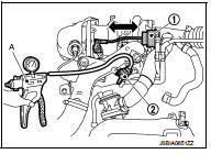

CAUTION:
Do not supply pressure over 70 kPa (700 mbar, 525 mmHg, 20.67 inHg)
Is the inspection result normal? YES >> INSPECTION END
NO >> Proceed to EC-258, "Diagnosis Procedure".
Diagnosis Procedure
1.CHECK BOOST CONTROL ACTUATOR HOSECheck disconnection, looseness or improper connection of hose between turbocharger boost control solenoid valve and boost control actuator.
Is the inspection result normal? YES >> GO TO 2.
NO >> Repair or replace error-detected parts.
2.CHECK TURBOCHARGER BOOST CONTROL SOLENOID VALVE POWER SUPPLY 1. Turn ignition switch OFF. 2. Disconnect turbocharger boost control solenoid valve harness connector.3. Turn ignition switch ON.
4. Check the voltage between turbocharger boost control solenoid valve harness connector and ground.
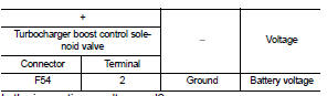
Is the inspection result normal? YES >> GO TO 4.
NO >> GO TO 3.
3.CHECK TURBOCHARGER BOOST CONTROL SOLENOID VALVE POWER SUPPLY CIRCUIT 1. Turn ignition switch OFF. 2. Disconnect IPDM E/R harness connector.3. Check the continuity between turbocharger boost control solenoid valve harness connector and IPDM E/R harness connector.

4. Also check harness for short to ground and short.
Is the inspection result normal? YES >> Perform the trouble diagnosis for power supply circuit.
NO >> Repair or replace error-detected parts.
4.CHECK TURBOCHARGER BOOST CONTROL SOLENOID VALVE GROUND CIRCUIT 1. Turn ignition switch OFF. 2. Disconnect ECM harness connector.3. Check the continuity between turbocharger boost control solenoid valve harness connector and ECM harness connector.

4. Also check harness for short to power.
Is the inspection result normal? YES >> GO TO 5.
NO >> Repair or replace error-detected parts.
5.CHECK TURBOCHARGER BOOST CONTROL SOLENOID VALVECheck the turbocharger boost control solenoid valve. Refer to EC-175, "Component Inspection".
Is the inspection result normal? YES >> GO TO 6.
NO >> Replace turbocharger boost control solenoid valve. Refer to EM-36, "Exploded View".
6.CHECK BOOST CONTROL ACTUATORCheck the boost control actuator. Refer to EM-37, "Inspection".
Is the inspection result normal? YES >> GO TO 7.
NO >> Replace exhaust manifold and turbocharger assembly. Refer to EM-36, "Exploded View".
7.CHECK TURBOCHARGER BOOST SENSORCheck the turbocharger boost sensor. Refer to EC-262, "Component Inspection".
Is the inspection result normal? YES >> Check intermittent incident. Refer to GI-42, "Intermittent Incident".
NO >> Replace turbocharger boost sensor. Refer to EM-31, "Exploded View".