Engine Control System MR16DDT

P0132 A/F sensor 1

In this manual: Engine Control System MR16DDT
Foreword — 1General information — 45Engine Mechanical MR16DDT — 61Engine Mechanical HR16DE — 52Engine Mechanical K9K — 46Engine Lubrication System MR16DDT — 18Engine Lubrication System HR16DE — 14Engine Lubrication System K9K — 11Engine Cooling System MR16DDT — 28Engine Cooling System HR16DE — 29Engine Cooling System K9K — 24Engine Control System MR16DDT — 163Engine Control System HR16DE — 115Engine Control System K9K — 129Fuel System MR16DDT — 13Fuel system HR16DE — 11Fuel system K9K — 12Exhaust system MR16DDT — 7Exhaust system HR16DE — 10Exhaust system K9K — 7Starting system — 24Accelerator control system — 6Clutch — 25Driveline transfer: TY21B — 77Driveline rear propeller Shaft: 3Fφ16-ETJ75 — 12Driveline rear final drive: RTVS — 31Transaxle & transmission 5MT: RS5F92R — 31Transaxle & transmission 6MT: RS6F94R — 30Transaxle & transmission CVT: RE0F10B — 93Transaxle & transmissioN CVT: RE0F11A — 103Front Axle MR16DDT — 18Front Axle HR16DE — 17Front Axle K9K — 17Rear Axle 2WD — 6Rear Axle 4WD — 13Front Suspension — 21Rear Suspension 2WD — 13Rear Suspension 4WD — 17Road Wheels & Tires — 6Brake System LHD — 24Brake System RHD — 24Parking Brake System — 8Brake Control System without ESP — 44Brake Control System with ESP — 63Steering System — 14Steering Control System — 27Seat Belt — 8SRS Airbag — 24SRS Airbag Control System — 93Ventilation System — 11Heater & Air Conditioning System HR16DE — 28Heater & Air Conditioning System MR16DDT — 28Heater & Air Conditioning Control System Type 1 — 49Heater & Air Conditioning Control System Type 2 — 51Heater & Air Conditioning Control System Type 3 — 32Heater & Air Conditioning Control System Type 4 — 40Heater & Air Conditioning Control System Type 5 — 21Interior — 16Instrument Panel — 10Seat — 18Door & Lock Type 1 — 83Door & Lock type 2 — 80Door & Lock type 3 — 65Door & Lock type 4 — 60Security Control System with intelligent key system — 82Security Control System without intelligent key system — 41Glass & Window System — 15Power Window Control System — 28Body Repair — 13Exterior — 20Mirrors — 26Exterior Lighting System Halogen type — 51Interior Lighting System — 24Wiper & Washer — 45Defogger — 31Horn — 4Power Outlet — 4Body Control System With intelligent key system — 21Body Control System Without intelligent key system — 23LAN system can fundamental — 6LAN system can — 31LAN System can system (type 1) — 1LAN System can system (type 2) — 1LAN System can system (type 3) — 1LAN System can system (type 4) — 1LAN System can system (type 5) — 1LAN System can system (type 6) — 1LAN System can system (type 7) — 2LAN System can system (type 8) — 1LAN System can system (type 9) — 1LAN System can system (type 10) — 1LAN System can system (type 11) — 1Power Control System IPDM E/R (with I-key) — 14Power Control System IPDM E/R (without I-key) — 14Power Control System Power distribution system — 25Charging System — 22Power Supply, Ground & Circuit Elements — 20Meter, Warning Lamp & Indicator — 33Warning Chime System — 22Audio, Visual & Navigation System Audio without navigation — 30Audio, Visual & Navigation System Audio with navigation — 33Audio, Visual & Navigation System NISSAN dynamic control system — 22Cruise Control System — 1Drive Mode System — 10Maintenance — 14
~3min read

DTC Logic

DTC DETECTION LOGIC

To judge the malfunction, the diagnosis checks that the A/F signal computed by ECM from the A/F sensor 1 signal is not inordinately high.
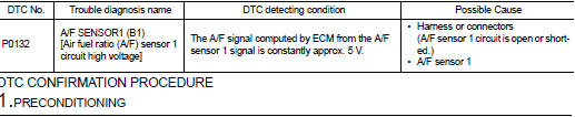
DTC CONFIRMATION PROCEDURE

DTC CONFIRMATION PROCEDURE

1.PRECONDITIONING

If DTC Confirmation Procedure has been previously conducted, always perform the following procedure before conducting the next test.

1. Turn ignition switch OFF and wait at least 10 seconds. 2. Turn ignition switch ON.

3. Turn ignition switch OFF and wait at least 10 seconds.

TESTING CONDITION:
Before performing the following procedure, confirm that battery voltage is more than 10.5 V at idle.

>> GO TO 2.

2.CHECK A/F SENSOR FUNCTION

1. Start engine and warm it up to normal operating temperature.With CONSULT-III


1. Start engine and warm it up to normal operating temperature. 2. Select “A/F SEN1 (B1)” in “DATA MONITOR” mode of “ENGINE” using CONSULT-III.

3. Check “A/F SEN1 (B1)” indication.

Follow the procedure “With CONSULT-III” above.With GST


Follow the procedure “With CONSULT-III” above.

Is the indication constantly approx. 5 V? YES >> Proceed to EC-213, "Diagnosis Procedure".

NO >> GO TO 3.

3.PERFORM DTC CONFIRMATION PROCEDURE

1. Turn ignition switch OFF, wait at least 10 seconds and then restartWith CONSULT-III


1. Turn ignition switch OFF, wait at least 10 seconds and then restart engine.

2. Drive and accelerate vehicle to more than 40 km/h within 20 seconds after restarting engine.

CAUTION:
Always drive vehicle at a safe speed.

3. Maintain the following conditions for about 20 consecutive seconds.

NOTE:

NOTE:
• Keep the accelerator pedal as steady as possible during the cruising.

• If this procedure is not completed within 1 minute after restarting engine at step 1, return to step 1.

4. Check 1st trip DTC.

Follow the procedure “With CONSULT-III” above. With GST


Follow the procedure “With CONSULT-III” above.

Is 1st trip DTC is detected? YES >> Proceed to EC-213, "Diagnosis Procedure".

NO >> INSPECTION END

Component Inspection

1.CHECK AIR FUEL RATIO (A/F) SENSOR 1 POWER SUPPLY 1. Turn ignition switch OFF. 2. Disconnect A/F sensor 1 harness connector. 3. Turn ignition switch ON.

4. Check the voltage between A/F sensor 1 harness connector and ground.
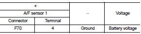
Is the inspection result normal?

Is the inspection result normal? YES >> GO TO 3.

NO >> GO TO 2.

2.CHECK AIR FUEL RATIO (A/F) SENSOR 1 POWER SUPPLY CIRCUIT 1. Turn ignition switch OFF. 2. Disconnect IPDM E/R harness connector.

3. Check the continuity between A/F sensor 1 harness connector and IPDM E/R harness connector.
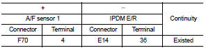
4. Also check harness for short to ground.

4. Also check harness for short to ground.

Is the inspection result normal? YES >> Perform the trouble diagnosis for power supply circuit.

NO >> Repair or replace error-detected parts.

3.CHECK A/F SENSOR 1 INPUT SIGNAL CIRCUIT 1. Turn ignition switch OFF. 2. Disconnect ECM harness connector.

3. Check the continuity between A/F sensor 1 harness connector and ECM harness connector.

4. Check the continuity between A/F sensor 1 harness connector and ground, or

4. Check the continuity between A/F sensor 1 harness connector and ground, or ECM harness connector and ground.


5. Also check harness for short to power.

5. Also check harness for short to power.

Is the inspection result normal? YES >> GO TO 4.

NO >> Repair or replace error-detected parts.

4.CHECK INTERMITTENT INCIDENT

Perform GI-42, "Intermittent Incident".

Is the inspection result normal? YES >> GO TO 5.

NO >> Repair or replace error-detected parts.

5.REPLACE AIR FUEL RATIO (A/F) SENSOR 1

Replace air fuel ratio (A/F) sensor 1. Refer to EM-38, "Exploded View".

CAUTION:
• Discard any sensor which has been dropped from a height of more than 0.5 m (19.7 in) onto a hard surface such as a concrete floor; use a new one.

• Before installing new sensor, clean exhaust system threads using Oxygen Sensor Thread Cleaner [commercial service tool (J-43897-18 or J43897-12)] and approved Anti-seize Lubricant (commercial service tool).

>> INSPECTION END