Electrical load signal
Description
The electrical load signal (Headlamp switch signal, rear window defogger switch signal, etc.) is transferred via the CAN communication line.
Component Function Check
1.CHECK REAR WINDOW DEFOGGER SWITCH FUNCTION With CONSULT-III
1. Turn ignition switch ON. 2. Select “DATA MONITOR” mode of “ENGINE” using CONSULT-III.
3. Select “LOAD SIGNAL” and check indication as per the following conditions.

Is the inspection result normal? YES >> GO TO 2.
NO >> Proceed to EC-418, "Diagnosis Procedure".
2.CHECK LIGHTING SWITCH FUNCTION With CONSULT-III
Check “LOAD SIGNAL” indication as per the following conditions.
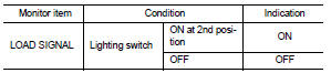
Is the inspection result normal? YES >> GO TO 3.
NO >> Proceed to EC-418, "Diagnosis Procedure".
3.CHECK HEATER FAN CONTROL SWITCH FUNCTION With CONSULT-III
Select “HEATER FAN SW” and check indication as per the following conditions.

Is the inspection result normal? YES >> INSPECTION END
NO >> Proceed to EC-418, "Diagnosis Procedure".
Diagnosis Procedure
1.INSPECTION STARTConfirm the malfunctioning circuit (rear window defogger, headlamp or heater fan). Refer to EC-418, "Component Function Check".
Which circuit is related to the incident? Rear window defogger>>GO TO 2.
Headlamp>>GO TO 3.
Heater fan>>GO TO 4.
2.CHECK REAR WINDOW DEFOGGER SYSTEMCheck the rear window defogger system. Refer to DEF-25, "Work Flow".
>> INSPECTION END 3.CHECK HEADLAMP SYSTEMCheck the headlamp system. Refer to EXL-43, "Work Flow".
>> INSPECTION END 4.CHECK HEATER FAN CONTROL SYSTEMCheck the heater fan control system. refer to HA-72, "Work Flow".
>> INSPECTION END