C1a13-23 Stop Lamp Rly Fix
DTC DETECTION LOGIC
| DTC No. | CONSULT screen items (Trouble diagnosis content) | DTC detection condition | |
|---|---|---|---|
| C1A13-23 | STOP LAMP RLY FIX (Stop lamp relay fix) |
Diagnosis condition | When engine is running |
| Signal (terminal) | — | ||
| Threshold | Stop lamp inactive state continues despite the outputting of an ADAS control unit stop lamp request signal | ||
| Diagnosis delay time | 1 second or more | ||
POSSIBLE CAUSE
Stop lamp switch circuit
Stop lamp switch
Incorrect stop lamp switch installation
ICC brake hold relay
ICC brake hold relay circuit
ADAS control unit
ECM
FAIL-SAFE
The following systems are canceled:
Vehicle-to-vehicle distance control mode
Conventional (fixed speed) cruise control mode
Automatic Emergency Braking (AEB) with pedestrian detection
Automatic Emergency Braking (AEB)
Intelligent Forward Collision Warning (I-FCW)
Rear Automatic Braking (RAB)
CHECK DTC PRIORITY
If DTC “C1A13–23” is displayed with DTC “U1000–01”, first diagnose the DTC “U1000–01”.
Is applicable DTC detected?
YES>>Perform diagnosis of applicable. Refer to DTC Description.
NO>>GO TO 2.
PERFORM DTC CONFIRMATION PROCEDURE (1)
 CONSULT
Start the engine.
Perform the active test item “STOP LAMP”.
Perform “All DTC Reading”.
Check if the “C1A13–23” is detected as the current malfunction in the “Self Diagnostic Result” of “ICC/ADAS”.
Is “C1A13–23” detected as the current malfunction?
YES>>Refer to DTC Diagnosis Procedure.
NO>>GO TO 3.
PERFORM DTC CONFIRMATION PROCEDURE (2)
CONSULT
Drive at the Nissan Murano vehicle speed of 40 km/h or more for approximately 20 seconds or more without the brake pedal depressed.
Perform “All DTC Reading”.
Check if the “C1A13–23” is detected as the current malfunction in the “Self Diagnostic Result” of “ICC/ADAS”.
Is “C1A13–23” detected as the current malfunction?
YES>>Refer to DTC Diagnosis Procedure.
NO>>To check malfunction symptom before repair: Refer to Intermittent Incident.
NO>>Confirmation after repair: Inspection End
CHECK DTC PRIORITY
If DTC “C1A13–23” is displayed with DTC “U1000–01”, first diagnose the DTC “U1000–01”.
Is applicable DTC detected?
YES>>Perform diagnosis of applicable. Refer to DTC Description.
NO>>GO TO 2.
CHECK STOP LAMP SWITCH
CONSULT
Select “Data Monitor” mode of “ICC/ADAS”.
Select “STOP LAMP SW”.
Check that the function operates normally according to the following conditions:
| Monitor item | Condition | Status |
| STOP LAMP SW | When brake pedal is applied | ON |
| When brake pedal is released | OFF |
Is the inspection result normal?
YES>>GO TO 10.
NO>>GO TO 3.
CHECK STOP LAMP SWITCH INSTALLATION
Turn ignition switch OFF.
Check stop lamp switch for correct installation. Refer to Inspection.
Is the inspection result normal?
YES>>GO TO 4.
NO>>Adjust stop lamp switch installation. Refer to Adjustment.
CHECK STOP LAMP SWITCH
Check stop lamp switch. Refer to Component Inspection (Stop Lamp Switch).
Is the inspection result normal?
YES>>GO TO 5.
NO>>Replace stop lamp switch. Refer to Exploded View.
CHECK STOP LAMP FOR ILLUMINATION
Remove ICC brake hold relay.
Check that the stop lamp is illuminated by depressing the brake pedal to turn the stop lamp ON.
Is the inspection result normal?
YES>>GO TO 6.
NO>>Check the stop lamp circuit, and repair or replace the malfunctioning parts.
CHECK HARNESS BETWEEN STOP LAMP SWITCH AND ECM
Turn the ignition switch OFF.
Disconnect stop lamp switch, ECM, rear combination lamp, and high-mounted stop lamp connectors.
Check for continuity between the stop lamp switch harness connector and the ECM harness connector.
Stop lamp switch ECM Continuity Connector Terminal Connector Terminal E38 2 E32 139 Yes Check for continuity between stop lamp switch harness connector and ground.
Stop lamp switch Ground Continuity Connector Terminal E38 2 No
Is the inspection result normal?
YES>>GO TO 7.
NO>>Repair the harnesses or connectors.
CHECK ICC BRAKE HOLD RELAY CIRCUIT
Connect ICC brake hold relay, ECM, rear combination lamp, and high-mounted stop lamp connectors.
Check that the stop lamp does not illuminate when brake pedal is not depressed.
Is the inspection result normal?
YES>>GO TO 9.
NO>>GO TO 8.
CHECK ICC BRAKE HOLD RELAY
Remove ICC brake hold relay.
Check ICC brake hold relay. Refer to Component Inspection.
Is the inspection result normal?
YES>>GO TO 9.
NO>>Replace ICC brake hold relay.
PERFORM SELF-DIAGNOSIS OF ECM
CONSULT
Connect all connectors again if the connectors are disconnected.
Turn ignition switch ON.
Perform “All DTC Reading”.
Check if any DTC is detected in “Self Diagnostic Result” of “ENGINE”. Refer to DTC Index.
Is any DTC detected?
YES>>Repair or replace the malfunctioning parts identified by the self-diagnosis result.
NO>>Replace ADAS control unit. Refer to Removal and Installation.
CHECK ICC BRAKE HOLD RELAY POWER SUPPLY CIRCUIT
Turn ignition switch OFF.
Remove ICC brake hold relay.
Check the voltage between ICC brake hold relay harness connector and ground.
Terminal Voltage
(Approx.)(+) (–) ICC brake hold relay Ground Connector Terminal E75 2 Battery voltage
Is the inspection result normal?
YES>>GO TO 11.
NO>>Repair or replace ICC brake hold relay power supply circuit.
CHECK HARNESS BETWEEN AND ICC BRAKE HOLD RELAY AND ADAS CONTROL UNIT
Disconnect ADAS control unit connectors.
Check for continuity between ICC brake hold relay harness connector and ADAS control unit harness connector.
ICC brake hold relay ADAS control unit Continuity Connector Terminal Connector Terminal E75 1 M182 4 Yes Check for continuity between ICC brake hold relay harness connector and ground.
ICC brake hold relay Ground Continuity Connector Terminal E75 1 No
Is the inspection result normal?
YES>>GO TO 12.
NO>>Repair the harnesses or connectors.
CHECK ICC BRAKE HOLD RELAY POWER SUPPLY CIRCUIT
Turn ignition switch OFF.
Check the voltage between ICC brake hold relay harness connector and ground.
Terminal Voltage
(Approx.)(+) (–) ICC brake hold relay Ground Connector Terminal E75 5 Battery voltage
Is the inspection result normal?
YES>>GO TO 13.
NO>>Repair or replace ICC brake hold relay power supply circuit.
CHECK HARNESS BETWEEN ICC BRAKE HOLD RELAY AND ECM
Disconnect ECM, rear combination lamp, and high-mounted stop lamp connectors and remove ICC brake hold relay.
Check for continuity between ICC brake hold relay harness connector and ECM harness connector.
ICC brake hold relay ECM Continuity Connector Terminal Connector Terminal E75 3 E32 139 Yes Check for continuity between ICC brake hold relay harness connector and ground.
ICC brake hold relay Ground Continuity Connector Terminal E75 3 No
Is the inspection result normal?
YES>>GO TO 14.
NO>>Repair the harnesses or connectors.
CHECK ICC BRAKE HOLD RELAY
Remove ICC brake hold relay.
Check ICC brake hold relay. Refer to Component Inspection.
Is the inspection result normal?
YES>>GO TO 15.
NO>>Replace ICC brake hold relay.
CHECK STOP LAMP SWITCH
CONSULT
Select “Data Monitor” mode of “ICC/ADAS”.
Select “STOP LAMP SW”.
Check that the function operates normally according to the following conditions:
| Monitor item | Condition | Status |
| STOP LAMP SW | When brake pedal is applied | ON |
| When brake pedal is released | OFF |
Is the inspection result normal?
YES>>GO TO 20.
NO>>GO TO 16.
CHECK STOP LAMP SWITCH INSTALLATION
Check stop lamp switch for correct installation. Refer to Inspection.
Is the inspection result normal?
YES>>GO TO 17.
NO>>Adjust stop lamp switch installation. Refer to Adjustment.
CHECK STOP LAMP SWITCH
Check stop lamp switch. Refer to Component Inspection (Stop Lamp Switch).
Is the inspection result normal?
YES>>GO TO 18.
NO>>Replace stop lamp switch. Refer to Exploded View.
CHECK STOP LAMP SWITCH POWER SUPPLY CIRCUIT
Check the voltage between stop lamp switch harness connector and ground.
| Terminal | Voltage (Approx.) |
||
| (+) | (–) | ||
| Stop lamp switch | Ground | ||
| Connector | Terminal | ||
| E38 | 3 | Battery voltage | |
| Terminal | Voltage (Approx.) |
||
| (+) | (–) | ||
| Stop lamp switch | Ground | ||
| Connector | Terminal | ||
| E38 | 1 | Battery voltage | |
Is the inspection result normal?
YES>>GO TO 19.
NO>>Repair or replace stop lamp switch power supply circuit.
CHECK HARNESS BETWEEN STOP LAMP SWITCH AND ABS ACTUATOR AND ELECTRIC UNIT (CONTROL UNIT)
Turn the ignition switch OFF.
Disconnect stop lamp switch and ABS actuator and electric unit (control unit).
Check for continuity between the stop lamp switch harness connector and the ABS actuator and electric unit (control unit) harness connector.
with ICC Stop lamp switch ABS actuator and electric unit (control unit) Continuity Connector Terminal Connector Terminal E38 4 E130 7 Yes without ICC Stop lamp switch ABS actuator and electric unit (control unit) Continuity Connector Terminal Connector Terminal E38 2 E125 30 Yes Check for continuity between stop lamp switch harness connector and ground.
with ICC Stop lamp switch Ground Continuity Connector Terminal E38 4 No without ICC Stop lamp switch Ground Continuity Connector Terminal E38 2 No
Is the inspection result normal?
YES>>GO TO 20.
NO>>Repair the harnesses or connectors.
PERFORM SELF-DIAGNOSIS OF ECM
CONSULT
Connect all connectors again if the connectors are disconnected.
Turn ignition switch ON.
Perform “All DTC Reading”.
Check if any DTC is detected in “Self Diagnostic Result” of “ENGINE”. Refer to DTC Index.
Is any DTC detected?
YES>>Repair or replace the malfunctioning parts identified by the self-diagnosis result.
NO>>GO TO 21.
PERFORM SELF-DIAGNOSIS OF ABS ACTUATOR AND ELECTRIC UNIT (CONTROL UNIT)
CONSULT
Connect all connectors again if the connectors are disconnected.
Turn ignition switch ON.
Perform “All DTC Reading”.
Check if any DTC is detected in “Self Diagnostic Result” of “ABS”. Refer to DTC Index.
Is any DTC detected?
YES>>Repair or replace the malfunctioning parts identified by the self-diagnosis result.
NO>>Replace ADAS control unit. Refer to Removal and Installation.
CHECK ICC BRAKE HOLD RELAY
Apply battery voltage to ICC brake hold relay terminals 1 and 2, and then check for continuity under the following conditions.
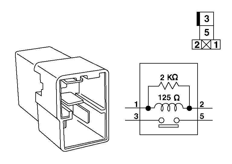
| Terminal | Condition | Continuity | |
|---|---|---|---|
| 3 | 5 | When the battery voltage is applied | Yes |
| When the battery voltage is not applied | No | ||
Is the inspection result normal?
YES>>Inspection End.
NO>>Replace ICC brake hold relay.