Brake compensator
These vehicles are fitted with a load-sensing brake compensator.
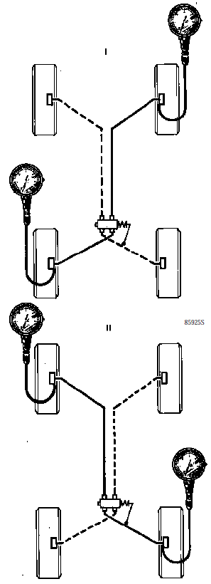
Pressure is read on the X circuit, by comparing the pressure at the rear wheels with a given pressure at the front wheels.
This dual compensator has two completely separate bodies which act in an X layout on one front wheel and one rear wheel.
Both circuits must be checked.
I: front right / rear left. II: front left / rear right.
Load-sensing compensator.
On load-sensing compensators, the adjustment sets the rear pressure in relation to the front pressure.
The adjustment acts on both bodies simultaneously. If the pressure is incorrect on only one of the two bodies, replace the compensator.
NOTE
brake compensators are differentiated according to the type of rear axle:
- rear axle with standard payload: red colour marking,
- rear axle with increased payload: green colour marking,
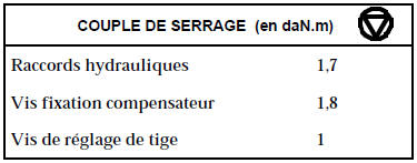
REMOVAL
Vehicle on a two-post lift.
Disconnect the brake pipes.
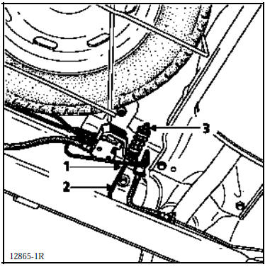
Disconnect rod (2) from the compensator by unscrewing screw (1).
Remove the compensator (two screws).
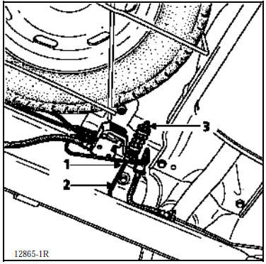
NOTE: do not alter the position of nut (3).
INSTALLATION
Refit in reverse order of removal.
Bleed and check the circuit (see section “Checking-Adjustment”).
CHECKING
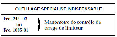
Connect two pressure gauges Fre. 244-03 or Fre. 1085-01:
- one on the front right,
- one on the rear left.
Bleed the gauges via screw (P).
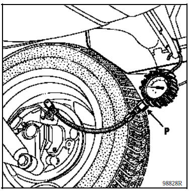
Gradually press the brake pedal until the setting pressure is reached at the front wheels (see values table).
Then read the corresponding pressure on the rear wheels; adjust it if necessary.
Repeat the same procedure on the other circuit, i.e.:
- one on the front left,
- one on the rear right.
If there is a significant difference (values outside tolerances), replace the proportioning valve. No adjustment is permitted.
ADJUSTMENT
The method of adjusting the proportioning valves currently used in the aftermarket is simple. It only requires two pressure gauges connected to the brake circuit (front right and rear left wheels, then front left and rear right wheels).
The check and adjustment are carried out with the vehicle unladen, fuel tank full and driver on board.
After applying a set pressure at the front by pressing the brake pedal, simply read the pressure at the rear and compare it with the value given in chapter 07. Then, adjust the proportioning valve rod by loosening the screw ( 1 ); this allows you to act on the rod ( 2 ).
NOTE: do not alter the position of nut (3).
This method is difficult to carry out when the vehicle is loaded, which is especially the case for commercial vehicles, generally equipped with shelving filled with spare parts and tools.
The case of these commercial vehicles requires another adjustment method based on calculating the tyre deflection (compression). This method is inexpensive but must be carried out carefully. Then, simply refer to the rear pressure curves established according to tyre deflection.
Required tools:
- a tape measure mounted on a base (used to measure underbody heights),
- a precision pressure gauge.
1 • Vehicle preparation:
- the vehicle must be left loaded,
- the person responsible for pressing the brake pedal during proportioning valve adjustment must be inside the vehicle when measuring the rear wheel loaded radius,
- the vehicle must be placed on a level, smooth and clean surface (the use of a four-post lift is most appropriate).
2 • Locating the centre of the rear wheels:
- raise the rear of the vehicle so the rear wheels can be turned,
- apply chalk to the hub cap or wheel trim at the point that appears closest to the centre of the wheel,
- turn the wheel by hand fairly quickly while pressing the chalk firmly; this operation draws concentric circles around the actual centre of rotation of the wheel,
- mark the centre with a cross in pencil on the chalk,
- repeat the same procedure on the second rear wheel.
3 • Inflating the rear tyres:
- the pressure must be set with the wheels on the ground and one person on board in the driver's seat,
- deflate both rear wheels to bring the pressure to 1.2 bar (use a correctly calibrated precision pressure gauge),
- wait a few minutes for the air in the tyres to return to ambient temperature, as it has cooled during expansion and its pressure has therefore changed,
- readjust the pressure to 1.2 bar as accurately as possible.
4 • Measuring the unloaded radius:
- lift the rear wheels so the tyres are no longer deformed by the axle load (as soon as the wheels leave the ground),
- measure the distance between the ground and the centre of the wheel with the tape measure.
5 • Measuring the loaded radius of the rear wheels:
- Lower the vehicle onto these wheels,
- measure the distance between the ground and the centre of the wheel with the tape measure.
6 • Calculating tyre deflection:
- subtract the two measurements obtained above to find the tyre deflection.
7 • Carry out steps 4, 5 and 6 for the second rear wheel.
8 • Calculating average tyre deflection of the two tyres:
- add the two deflection values found for the two rear wheels, then divide the result by two to determine the average deflection.
9 • Reading the charts:
- On the first chart, read the rear axle load corresponding to the average deflection found.
- Refer to the second chart and read the output pressure P2 (corresponding to the pressure applied to each rear wheel) for the load value found on the first chart.
WARNING: a chart corresponds to one tyre brand and type.
Rear axle load / tyre deflection (pressure 1.2 bar)
DUNLOP 165/70 R13C
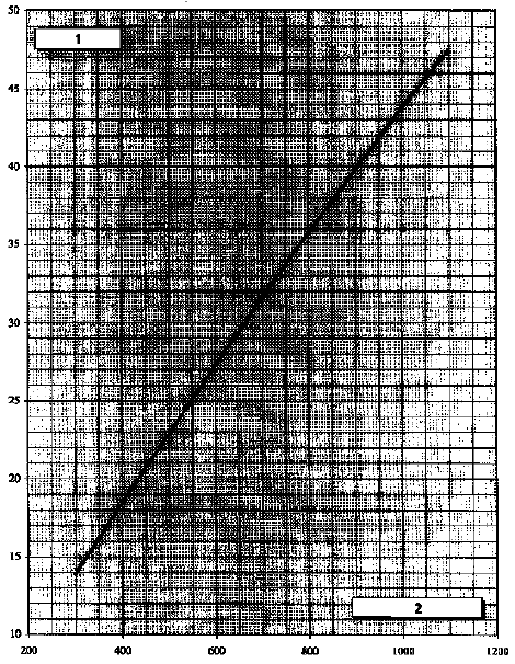
- Deflection (mm)
- Rear axle load (kg)
Rear axle load / tyre deflection (pressure 1.2 bar)
KLEBER 165/70 R13
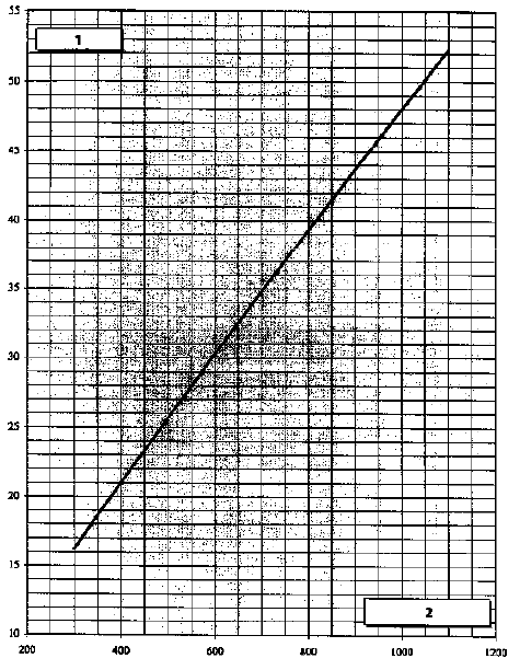
- Deflection (mm)
- Rear axle load (kg)
Rear axle load / tyre deflection (pressure 1.2 bar)
MICHELIN 165/70 R13C XC4S
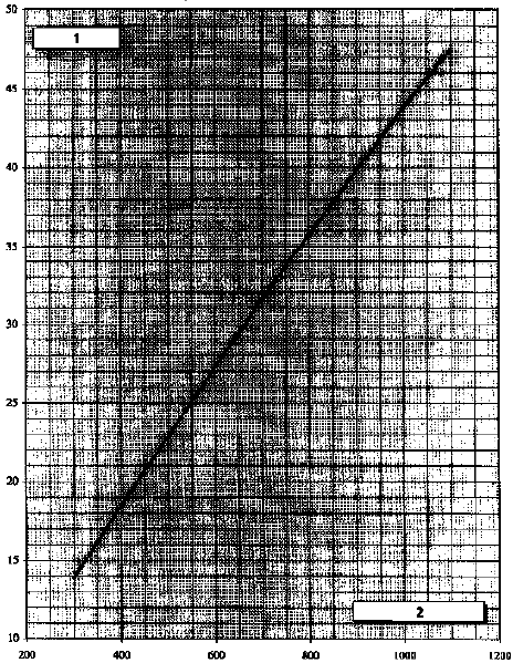
- Deflection (mm)
- Rear axle load (kg)
Rear axle load / tyre deflection (pressure 1.2 bar)
MICHELIN 165/70 R13C Agilis 61
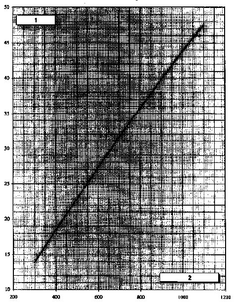
- Deflection (mm)
- Rear axle load (kg)
Proportioning valve output pressure adjustment / Rear axle load
KANGOO standard payload
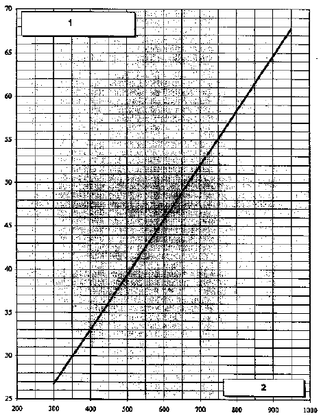
- Output pressure P2 (bar) for 100 bar at the front
- Rear axle load (kg)
Proportioning valve output pressure adjustment / Rear axle load
KANGOO increased payload
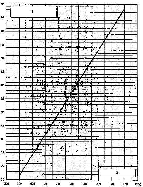
- Output pressure P2 (bar) for 100 bar at the front
- Rear axle load (kg)
Test yourself
A quick Renault Kangoo quiz: every answer comes with an explanation and a link to the manual page.