DCT (Dual Clutch Transmission) System
Clutch Actuator Assembly Repair Procedures
In this manual: DCT (Dual Clutch Transmission) System
41steps
~261min
5/5difficulty
3special tools
Done 0 of 41
Removal
- Remove the air cleaner assembly and air duct. (Refer to Engine Mechanical System - "Air Cleaner")
- Remove the TCM. (Refer to Dual Clutch Transmission - "TCM")
- Remove the battery and tray. (Refer to Engine Electrical System — "Battery")
- Disconnect the clutch actuator connector (A).

- Remove the under cover. (Refer to Engine Mechanical System - "Engine Room Under Cover")
- Remove the fork cover after loosening the bolt (A-2ea).
Tightening torque: 3.9 ~ 5.9 N·m
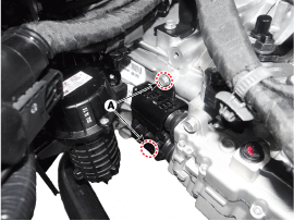
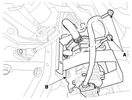
- Remove the vacuum pump (B) by loosening the bracket mounting bolts (A-2ea).
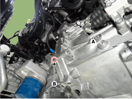
- Remove the starter motor mounting bolts (S) and the lower mounting bolt (B).
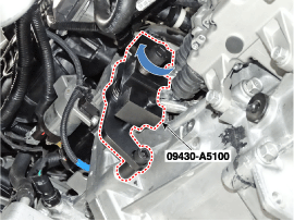
- Secure the clutch release fork by turning the bolt after installing the Special Service Tool (09430-A5100).
- Remove the clutch actuator assembly from the transmission after loosening the bolts (A-3ea).

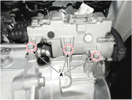
Inspection
- Remove the clutch actuator. (Refer to Clutch Actuator Assembly - "Removal")
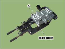
- Install the clutch actuator (A) on the Special Service Tool (09430-C1302) and secure the actuator with the nuts.
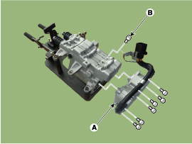
- Remove the clutch actuator motor (A) and the ground bolt (B).
- Insert the Special Service Tool (09430-C1302) into the ball screw and turn counterclockwise until a click is heard.

- If no click is heard, turn the ball screw counterclockwise until it stops.
- Be very careful not to keep turning the screw counterclockwise when it is at the end position, as this may cause damage to the actuator.

- Measure the length (C) from the base plane (A) to the end of the rod (B).
C Service Standard: 25 mm (0.9843 in.)
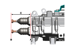
- If the rod length is approximately 25 mm (0.9843 in.) less than specified, replace the dual clutch and clutch actuator assembly, and the bearing carrier.
Installation
- Install in the reverse order of removal.

- Perform the procedure to reset the wear compensation before installing the new clutch actuator assembly. (Refer to Clutch Actuator Assembly - "Adjustment")
- Check the assembled condition of the installation pins (A) before installing the clutch actuator assembly.
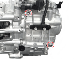
- Perform the clutch touch point learning procedure using GDS after replacing the clutch actuator assembly.
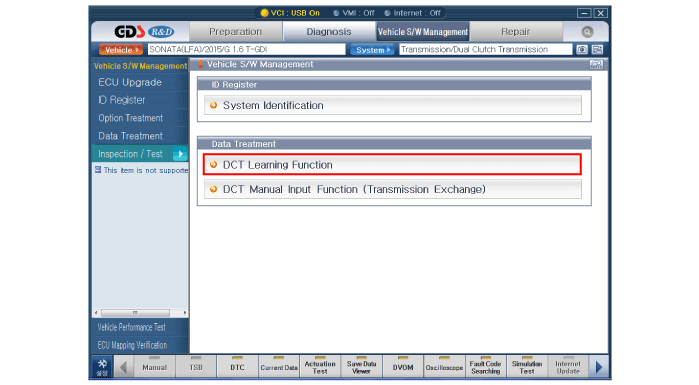
Adjustment
|

How to Rewind the Wear Compensation
- Remove the clutch actuator assembly. (Refer to Clutch Actuator Assembly - Removal)
- Install the faulty clutch actuator (A) on the Special Service Tool (09430-C1302) and secure the actuator with the nuts.
- Remove the clutch actuator motor (A) and the ground bolt (B).
- Insert the Special Service Tool (09430-C1302) into the ball screw and turn counterclockwise until a click is heard.
- If no click is heard, turn the ball screw counterclockwise until it stops.
- Be very careful not to keep turning the screw counterclockwise when it is at the end position, as this may cause damage to the actuator.
- Measure the length (C) from the base plane (A) to the end of the rod (B).
- Pull the lever (A) until it clicks, then measure the length to check the rod length of the faulty clutch actuator (B).
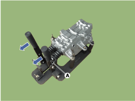
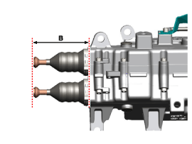
- Remove the clutch actuator from the special service tool (09430-C1302).
- Install the new clutch actuator (A) on the Special Service Tool (09430-C1302) and secure the actuator with the nuts.
- Remove the clutch actuator motor (A) and the ground bolt (B).
- Insert the Special Service Tool (09430-C1302) into the ball screw and turn counterclockwise until a click is heard.
- If no click is heard, turn the ball screw counterclockwise until it stops.
- Be very careful not to keep turning the screw counterclockwise when it is at the end position, as this may cause damage to the actuator.
- Secure the rod on the hook (B) and remove the rubber boot (A).
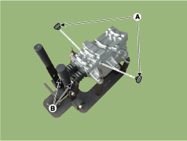
- Insert the Special Service Tool (09430-C1300) into the rubber seal hole, then adjust the rod length to match the length of the previous clutch actuator rod by turning it clockwise.
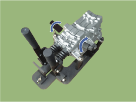
- Pull the lever (A) until it clicks, then measure the length to check the rod (B).
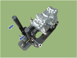
- Install the rubber seal (A).
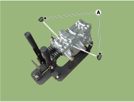
- Install the clutch actuator motor (A) and the ground bolt (B) with the O-ring (C).
Check the O-rings (C) and install them carefully.Tightening torque: 3.9 ~ 5.9 N·m
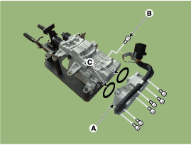
How to Initialize the Wear Compensation
- Remove the clutch actuator assembly. (Refer to Clutch Actuator Assembly - Removal)
- Install the clutch actuator (A) on the Special Service Tool (09430-C1302) and secure the actuator with the nuts.
- Remove the clutch actuator motor (A).
- Insert the Special Service Tool (09430-C1302) into the ball screw and turn counterclockwise until a click is heard.
- If no click is heard, turn the ball screw counterclockwise until it stops.
- Be very careful not to keep turning the screw counterclockwise when it is at the end position, as this may cause damage to the actuator.
- Tighten the nut (A) after installing the T-plates (B) at 49 mm (1.9291 in.).
- Remove the rubber seal (C).
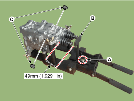
- Insert the Special Service Tool (09430-C1300) into the hole of the rubber seal, then move it toward the T-plates (A) by turning clockwise.
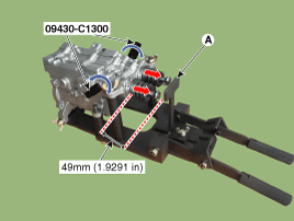
- Secure the rod to the hook (B) and install the rubber seal (A).
- Pull the lever (A) until it clicks, then measure the length again to check that it matches the specified length (B).
Specified length: 71.5 mm (2.8150 in.)
- Install the clutch actuator motor (A) and the weight (B).
Check the O-rings (C-2ea) and install them carefully.Tightening torque: 3.9 ~ 5.9 N·m
Test yourself
A quick Hyundai Sonata LF quiz: every answer comes with an explanation and a link to the manual page.
Was this page helpful?