Electric Parking Brake System AUTO Operation Circuit
DESCRIPTION
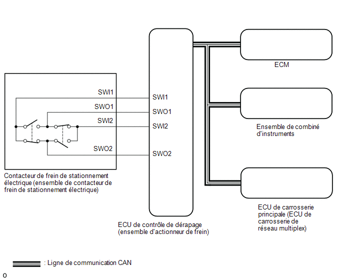
The Skid Control ECU (brake actuator assembly) receives gear position information from the ECM via the CAN communication system.
In addition, the front seat belt buckle information and the driver door courtesy light switch information are received by the Main Body ECU (Multiplex Network Body ECU).
The Electric Parking Brake System AUTO function (shift-linked) automatically releases the parking brake when the following conditions are met: 1) the ignition switch is in ON, 2) the brake pedal is depressed, and 3) the shift lever is moved to a position other than P. When the shift lever is moved to P while these conditions are met, this function automatically applies the parking brake.
The Electric Parking Brake System AUTO function (shift-linked function) automatically applies the parking brake when the shift lever is moved to P, and releases the parking brake when the shift lever is moved to a position other than P with the ignition switch in ON and the brake pedal depressed.
WIRING DIAGRAM
PRECAUTION / NOTICE / HINT
NOTICE:
- The electric parking brake may still operate for 20 seconds after the ignition switch is turned OFF. Before disconnecting connectors or fuses, turn the ignition switch OFF and wait at least 20 seconds.
- When replacing the skid control ECU (brake actuator assembly), operate the electric parking brake switch assembly while the parking brake indicator flashes (red) if the ignition switch is turned to ON for the first time.
PROCEDURE
INSPECT CAN COMMUNICATION SYSTEM
(a) Check whether CAN communication system DTCs are output.
Click here
Result:
Result | Proceed to |
|---|---|
No DTCs are output |
A |
DTCs are output |
B |
| B |  |
GO TO CAN COMMUNICATION SYSTEM |
|

READ VALUE USING TECHSTREAM (AUTO MODE)
(a) Turn the ignition switch OFF.
(b) Connect the Techstream to the DLC3.
(c) Turn the ignition switch to ON.
(d) Turn on the Techstream.
(e) Select the following menu items: Chassis / ABS/VSC/TRAC/EPB / Data List.
(f) Read the Data List by following the Techstream instructions.
Chassis > ABS/VSC/TRAC/EPB > Data ListTester display | Item | Range | Normal Condition | Diagnostic Note |
|---|---|---|---|---|
Auto Mode |
AUTO Mode Permission Status (linked to shift operation) |
ON or OFF |
OFF: Manual mode ON: AUTO mode (linked to shift operation) |
- |
Auto Mode
(g) When switching the mode, check that the Data List screen turns on and off.
Result:
Result | Proceed to |
|---|---|
The AUTO indicator does not turn on and off when the Active Test is set to ON and OFF. |
A |
The AUTO indicator turns on and off when the Active Test is set to ON and OFF. |
B |
| B | |
GO TO STEP 5 |
|
INSPECT ELECTRIC PARKING BRAKE SWITCH (ELECTRIC PARKING BRAKE SWITCH ASSEMBLY)
(a) Inspect the electric parking brake switch (electric parking brake switch assembly).
Click here
| NG | |
REPLACE ELECTRIC PARKING BRAKE SWITCH (ELECTRIC PARKING BRAKE SWITCH ASSEMBLY) |
|
INSPECT WIRE HARNESS AND CONNECTOR (SKID CONTROL ECU (BRAKE ACTUATOR ASSEMBLY) - ELECTRIC PARKING BRAKE SWITCH (ELECTRIC PARKING BRAKE SWITCH ASSEMBLY))
(a) Disconnect connector F67 from the electric parking brake switch (electric parking brake switch assembly).
(b) Disconnect the A42 connector from the Skid Control ECU (Brake Actuator Assembly).
(c) Measure the resistance according to the value(s) in the table below.
Standard resistance:
Tester Connection | Condition | Specified Condition |
|---|---|---|
A42-31 (SWI1) - F67-6 (SWI1) |
Always |
Below 5 Ω |
A42-32 (SWO1) - F67-5 (SWO1) |
Always |
Below 5 Ω |
A42-15 (SWI2) - F67-4 (SWI2) |
Always |
Below 5 Ω |
A42-16 (SWO2) - F67-3 (SWO2) |
Always |
Below 5 Ω |
A42-31 (SWI1) or F67-6 (SWI1) - Body ground |
Always |
10 kΩ minimum |
A42-32 (SWO1) or F67-5 (SWO1) - Body ground |
Always |
10 kΩ minimum |
A42-15 (SWI2) or F67-4 (SWI2) - Body ground |
Always |
10 kΩ minimum |
A42-16 (SWO2) or F67-3 (SWO2) - Body ground |
Always |
10 kΩ minimum |
| NG | |
REPAIR OR REPLACE HARNESS OR CONNECTOR |
|
READ VALUE USING TECHSTREAM (SHIFT POSITION)
(a) Turn the ignition switch OFF.
(b) Connect the Techstream to the DLC3.
(c) Turn the ignition switch to ON.
(d) Turn on the Techstream.
(e) Select the following menu items: Chassis / ABS/VSC/TRAC/EPB / Data List.
(f) Read the Data List by following the Techstream instructions.
Chassis > ABS/VSC/TRAC/EPB > Data ListTester display | Item | Range | Normal Condition | Diagnostic Note |
|---|---|---|---|---|
Shift Position |
Shift lever position information |
"P,N", R, D/M, 1st-6th/B or Fail |
Actual shift lever position |
- |
OK:
On the Techstream screen, ON or OFF is displayed accordingly.
Chassis > ABS/VSC/TRAC/EPB > Data ListShift Lever Position
| NG | |
GO TO CONTINUOUSLY VARIABLE TRANSAXLE SYSTEM |
|
READ VALUE USING TECHSTREAM (STOP LIGHT SW)
(a) Turn the ignition switch OFF.
(b) Connect the Techstream to the DLC3.
(c) Turn the ignition switch to ON.
(d) Turn on the Techstream.
(e) Select the following menu items: Chassis / ABS/VSC/TRAC/EPB / Data List.
(f) Read the Data List by following the Techstream instructions.
Chassis > ABS/VSC/TRAC/EPB > Data ListTester display | Item | Range | Normal Condition | Diagnostic Note |
|---|---|---|---|---|
Stop Light SW |
Stop light switch |
OFF or ON |
ON: Brake pedal depressed OFF: Brake pedal released |
- |
Stop Light SW
OK:
On the Techstream screen, ON or OFF is displayed accordingly.
| OK | |
REPLACE SKID CONTROL ECU (BRAKE ACTUATOR ASSEMBLY) |
|
READ VALUE USING TECHSTREAM (DOOR COURTESY SW)
(a) Turn the ignition switch OFF.
(b) Connect the Techstream to the DLC3.
(c) Turn the ignition switch to ON.
(d) Turn on the Techstream.
(e) Select the following menu items: Body Electrical > Main Body > Data List
(f) Read the Data List by following the Techstream instructions.
Body Electrical > Main Body > Data ListTester display | Item | Range | Normal Condition | Diagnostic Note |
|---|---|---|---|---|
FL Door Courtesy SW |
Front left door courtesy light switch assembly |
ON or OFF |
ON: Front left door open OFF: Front left door closed |
If this item does not change according to the actual position of the driver's door, there is a malfunction in the door courtesy light switch or a related part. |
FL Door Courtesy SW
OK:
The Data List item changes as the driver door is opened and closed.
| NG | |
GO TO ILLUMINATION SYSTEM |
|
READ VALUE USING TECHSTREAM (D SEAT BUCKLE SW)
(a) Turn the ignition switch OFF.
(b) Connect the Techstream to the DLC3.
(c) Turn the ignition switch to ON.
(d) Turn on the Techstream.
(e) Select the following menu items: Body Electrical > Main Body > Data List
(f) Read the Data List by following the Techstream instructions.
Body Electrical > Main Body > Data ListTester display | Item | Range | Normal Condition | Diagnostic Note |
|---|---|---|---|---|
D Seat Buckle SW |
Driver Seat Belt Buckle Switch |
OFF or ON |
ON: Driver seat belt not fastened OFF: Driver seat belt fastened |
- |
D Seat Buckle SW
OK:
Unset or Set is displayed on the Techstream depending on the driver seat belt status.
| OK | |
REPLACE SKID CONTROL ECU (BRAKE ACTUATOR ASSEMBLY) |
| NG | |
GO TO SEAT BELT WARNING SYSTEM |