Cylinder head gasket (1MZ−FE/3MZ−FE)
- WORK FOR PREVENTING GASOLINE FROM SPILLING OUT
- DRAIN ENGINE COOLANT
- DRAIN ENGINE OIL
- REMOVE EXHAUST PIPE No.1 SUPPORT BRACKET
- REMOVE EXHAUST PIPE ASSY FRONT
- REMOVE EXHAUST MANIFOLD SUB−ASSY RH
- REMOVE V−BANK COVER SUB−ASSY
- REMOVE FRONT SUSPENSION UPPER BRACE CENTER (W/ FRONT SUSPENSION BRACE UPPER CENTER)
- REMOVE AIR CLEANER ASSEMBLY WITH HOSE
- REMOVE INTAKE AIR SURGE TANK
- DISCONNECT FUEL PIPE SUB−ASSY No.1
- DISCONNECT HEATER INLET WATER HOSE
Lock the hose clamp as shown in the illustration.
Disconnect the heater inlet water hose.
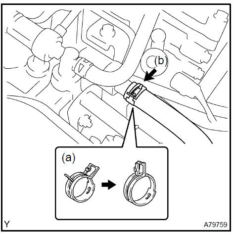
Disconnect heater inlet water hose 13. REMOVE INTAKE MANIFOLD
Remove the nut and disconnect the ground cable.
Disconnect the 6 fuel injector connectors.
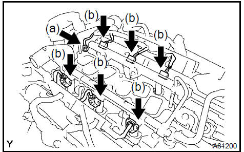
c. Uniformly loosen and remove the intake manifold’s 9 bolts and 2 nuts in the sequence shown in the illustration. Remove the intake manifold.

- DISCONNECT RADIATOR HOSE INLET
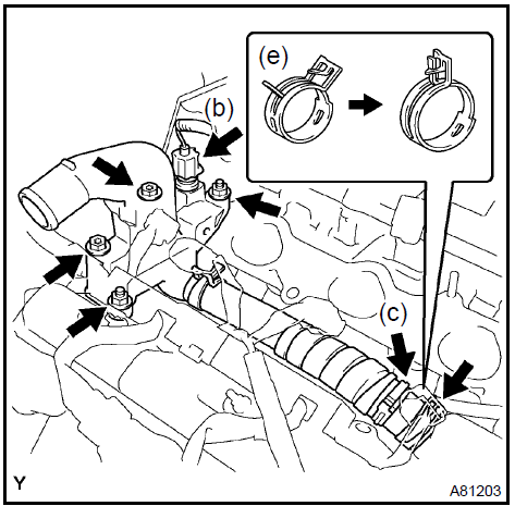
- REMOVE WATER OUTLET
Disconnect the radiator hose inlet.
Disconnect the engine coolant temperature connector.
Remove the clamp.
Remove the 2 bolts, 2 nuts and 2 washers.
Lock the hose clamp as shown in the illustration and remove the water outlet together with the water by−pass hose No. 1.
Remove the 2 gaskets from the 2 cylinder heads.
- REMOVE FRONT WHEEL RH
- REMOVE FRONT FENDER APRON SEAL RH
- REMOVE V (COOLER COMPRESSOR TO CRANKSHAFT PULLEY) BELT No.1
- REMOVE VANE PUMP V BELT
- REMOVE ENGINE MOVING CONTROL ROD
- REMOVE ENGINE MOUNTING STAY No.2 RH
- REMOVE GENERATOR BRACKET No.2
- REMOVE CRANKSHAFT PULLEY
- REMOVE TIMING BELT No.1 COVER
- REMOVE TIMING BELT No.2 COVER
- REMOVE ENGINE MOUNTING BRACKET RH
- REMOVE TIMING BELT GUIDE No.2
- REMOVE TIMING BELT
- REMOVE TIMING BELT IDLER SUB−ASSY No.2
- REMOVE CAMSHAFT TIMING PULLEY
- REMOVE TIMING BELT No.3 COVER
- REMOVE VANE PUMP ASSY
- REMOVE IGNITION COIL ASSY
- REMOVE CYLINDER HEAD COVER SUB−ASSY
- REMOVE CAMSHAFT
- REMOVE No.2 CAMSHAFT
- REMOVE CYLINDER HEAD SUB−ASSY
Disconnect the VVT connector.
Disconnect the camshaft timing oil control valve connector.
Remove the nut and disconnect the engine wire harness clamp.
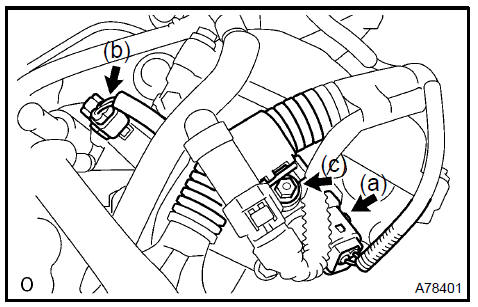
d. Using a socket hexagon wrench 8, remove the hexagon bolt.
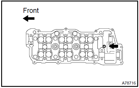
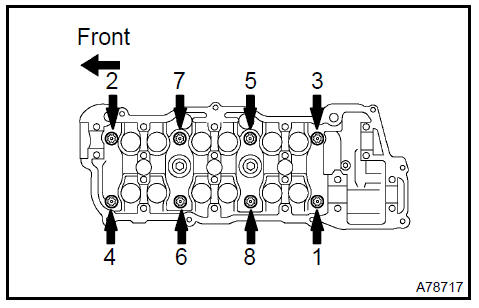
e. Uniformly loosen the 8 cylinder head bolts in the sequence shown in the illustration. Remove the 8 cylinder head bolts and plate washers.
NOTICE:- Be careful not to drop the washers into the cylinder head.
- Head warpage or cracking could result from removing bolts in an incorrect order.
- REMOVE CYLINDER HEAD GASKET
- INSPECT CYLINDER HEAD SET BOLT
a. Using a vernier caliper, measure the tension portion diameter of the bolt.
Specified outside diameter: 8.75 to 9.05 mm (0.3445 to 0.3563 in.)If the diameter is less than the minimum, replace the bolt.

Inspect cylinder head set bolt 40. INSTALL CYLINDER HEAD GASKET
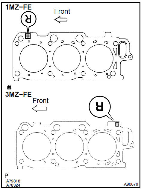
a. Place a new cylinder head gasket on the cylinder block with the R mark upside down, as shown in the illustration.
NOTICE:- Remove any oil from the contact surface.
- Be careful of the installation direction.
- To avoid damage to the gasket, place the cylinder head on the gasket carefully.
Apply a light coat of engine oil on the threads of the cylinder head bolts.
Install the plate washers to the cylinder head bolts.
Uniformly install and tighten the 8 cylinder head bolts in the sequence shown in the illustration.
Torque: 54 N·m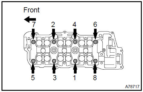
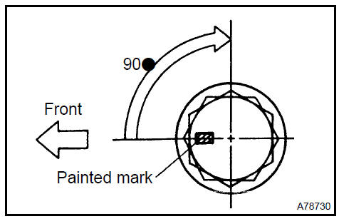
Mark the front side of each cylinder head bolt head with paint as shown in the illustration.
Retighten the cylinder head bolts by 90 in the same sequence as step c..
Check that each painted mark is now at a 90 angle to the front.
Using a socket hexagon wrench 8, install the hexagon bolt.
Torque: 19 N·mConnect the engine wire harness clamp with the nut.
Torque: 8,4 N·m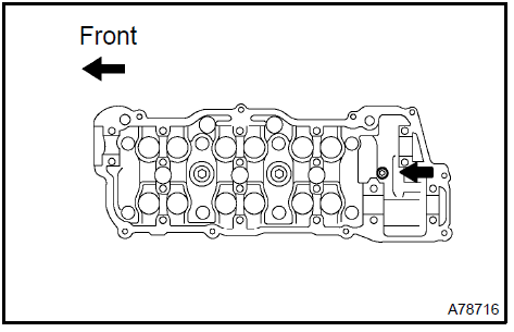
- INSTALL No.2 CAMSHAFT
- INSTALL CAMSHAFT
- INSTALL CYLINDER HEAD COVER SUB−ASSY
- INSTALL IGNITION COIL ASSY Torque: 8 N·m
- INSTALL VANE PUMP ASSY
- INSTALL TIMING BELT No.3 COVER
- INSTALL CAMSHAFT TIMING PULLEY
- INSTALL TIMING BELT IDLER SUB−ASSY No.2 Torque: 43 N·m
- INSPECT TIMING BELT
- INSTALL TIMING BELT
- INSTALL TIMING BELT TENSIONER ASSY
- INSTALL TIMING BELT GUIDE No.2
- INSTALL ENGINE MOUNTING BRACKET RH Torque: 28 N·m
- INSTALL TIMING BELT No.2 COVER
- INSTALL TIMING BELT No.1 COVER
- INSTALL CRANKSHAFT PULLEY
- INSTALL GENERATOR BRACKET No.2 Torque: 28 N·m
- INSTALL ENGINE MOUNTING STAY No.2 RH
- INSTALL ENGINE MOVING CONTROL ROD
- INSTALL VANE PUMP V BELT
- INSTALL V (COOLER COMPRESSOR TO CRANKSHAFT PULLEY) BELT No.1
- INSPECT DRIVE BELT TENSION
- INSTALL WATER OUTLET
Install 2 new gaskets to the 2 cylinder heads.
Install the water outlet together the with water by−pass hose No. 1 and unlock the hose clamp.
Tighten the 2 bolts, 2 nuts and 2 washers.
Torque: 15 N·mInstall the clamp.
Connect the engine coolant temperature connector.
Connect the radiator hose inlet.
Install the intake manifold with the 9 bolts, 2 nuts and 2 washers. Uniformly tighten the bolts and nuts in the sequence shown in the illustration.
Torque: 15 N·mRetighten the water outlet mounting bolts and nuts.
Torque: 15 N·mInstall the ground cable with the nut.
Torque: 8,4 N·mConnect the heater inlet water hose.
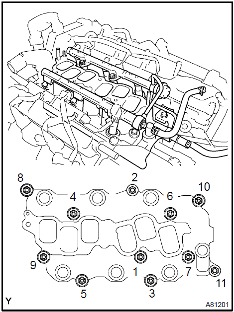
Install intake manifold
- CONNECT FUEL PIPE SUB−ASSY No.1
- INSTALL INTAKE AIR SURGE TANK
- INSTALL AIR CLEANER ASSEMBLY WITH HOSE
- CONNECT VACUUM HOSES
- INSTALL FRONT SUSPENSION UPPER BRACE CENTER (W/ FRONT SUSPENSION BRACE UPPER CENTER) Torque: 80 N·m
- INSTALL V−BANK COVER SUB−ASSY
- INSTALL EXHAUST MANIFOLD SUB−ASSY RH
- INSTALL EXHAUST PIPE ASSY FRONT
- INSTALL EXHAUST PIPE No.1 SUPPORT BRACKET
- INSTALL FRONT WHEEL RH
- ADD ENGINE OIL
- ADD ENGINE COOLANT
- CHECK FOR ENGINE OIL LEAKS
- CHECK FOR ENGINE COOLANT LEAKS
- CHECK FOR FUEL LEAKS
- CHECK FOR EXHAUST GAS LEAKS
- INSPECT IGNITION TIMING
- INSPECT ENGINE IDLE SPEED
- INSPECT COMPRESSION
- INSPECT CO/HC
Test yourself
A quick Toyota Camry quiz: every answer comes with an explanation and a link to the manual page.