REMOVE FRONT SUSPENSION UPPER BRACE CENTER (W/ FRONT SUSPENSION BRACE UPPER CENTER)
DRAIN COOLANT
DISCONNECT RADIATOR HOSE OUTLET
DISCONNECT UNION TO CONNECTOR TUBE HOSE
SCONNECT HEATER INLET WATER HOSE
DISCONNECT FUEL TUBE SUB−ASSY
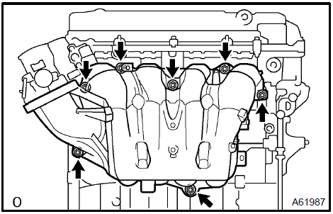
REMOVE INTAKE MANIFOLD
Disconnect the 2 Ωater by−pass hoses of the throttle body.
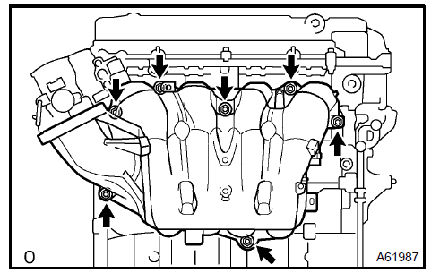
Remove the 5 bolts, 2 nuts, intake manifold and gasket.
Remove intake manifold
REMOVE INTAKE MANIFOLD RUNNER VALVE ASSY
DISCONNECT ENGINE WIRE
REMOVE INTAKE MANIFOLD INSULATOR No.1
REMOVE EXHAUST MANIFOLD HEAT INSULATOR No.1
REMOVE EXHAUST MANIFOLD CONVERTER SUB−ASSY
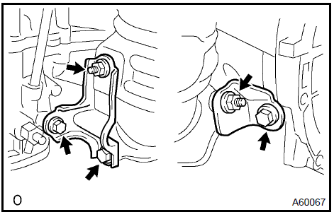
a. Remove the 3 bolts, 2 nuts, No. 1 and No. 2 exhaust manifold stays.
b. Remove the 5 nuts, exhaust manifold and gasket.
REMOVE CHAIN SUB−ASSY
REMOVE No.2 CAMSHAFT
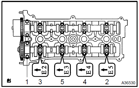
Uniformly loosen and remove the No. 2 camshaft’s 10 bearing cap bolts in the sequence shown in the illustration.
Then remove the 5 bearings.
Remove the camshaft.
Remove No.2 Camshaft16. REMOVE CAMSHAFT
Uniformly loosen and remove the No. 2 camshaft’s 10 bearing cap bolts in the sequence shown in the illustration.
Then remove the 5 bearings.
Remove the camshaft.
Remove camshaft
REMOVE CAMSHAFT BEARING No.2
REMOVE CAMSHAFT TIMING OIL CONTROL VALVE ASSY
REMOVE CYLINDER HEAD SUB−ASSY
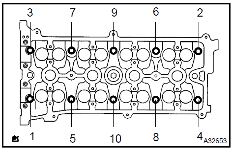
a. Using a 10 mm bi−hexagon wrench, uniformly loosen the 10 bolts in the sequence shown in the illustration. Remove the 10 cylinder head bolts and plate washers.
NOTICE:
Be careful not to drop washers into the cylinder head.
Head warpage or cracking could result from removing bolts in an incorrect order.
Remove cylinder head sub-assy
REMOVE CYLINDER HEAD GASKET
INSPECT CYLINDER HEAD SET BOLT
a. Using a vernier caliper, measure the length of the head bolts from the seat to the end.Specified bolt length:161.3 to 164.2 mm (6.350 to 6.465 in.)
If the length is greater than the maximum, replace the bolt.
Inspect cylinder head set bolt22. INSTALL CYLINDER HEAD GASKET
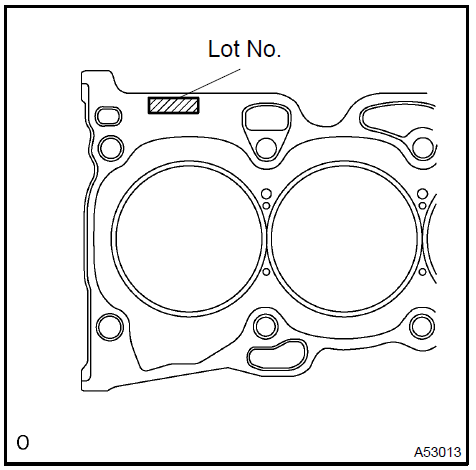
a. Place a new gasket on the cylinder block surface with the Lot No. stamp upward.
NOTICE:
Remove any oil from contact surface.
Be careful of the installation direction.
To avoid damage to the gasket, place the cylinder head on the gasket carefully.
23. INSTALL CYLINDER HEAD SUB−ASSY
HINT: The cylinder head bolts are tightened in 2 progressive steps.
Apply a light coat of engine oil on the threads and under the heads of the cylinder head bolts.
Install the bolts and plate washers to the cylinder head.
NOTICE: Do not drop the washers into the cylinder head. c. Using a 10 mm bi−hexagon wrench, uniformly tighten the 10 bolts in the sequence shown in the illustration.Torque: 79 N·m
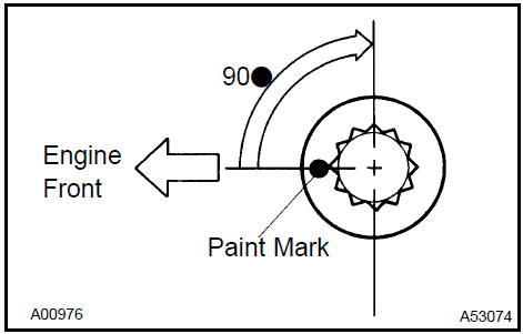
Mark the front side of the cylinder head bolt with paint.
Retighten the cylinder head bolts by 90 in the sequence shown in the illustration.
Check that the painted mark is now at a 90 angle to the front.
INSTALL CAMSHAFT TIMING OIL CONTROL VALVE ASSY Torque: 9 N·m
INSTALL CAMSHAFT BEARING No.2
INSTALL CAMSHAFT
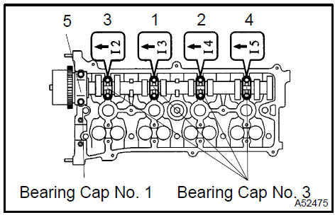
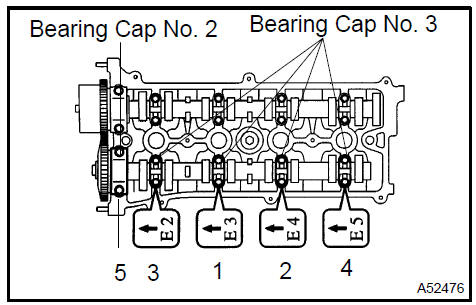
a. Examine the front marks and numbers of the 5 bearing caps and install them. Then install the 10 bearing cap bolts. Uniformly tighten the bolts in the sequence shown in the illustration.Torque: 30 N·m for bearing cap No. 1 9 N·m for bearing cap No. 3Install camshaft27. INSTALL No.2 CAMSHAFT a. Examine the front marks and numbers of the 5 bearing caps and install them. Then install the 10 bearing cap bolts. Uniformly tighten the bolts in the sequence shown in the illustration.Torque: 30 N·m for bearing cap No.2 9 N·m for bearing cap No.3Install No.2 Camshaft
INSTALL CHAIN SUB−ASSY
INSTALL EXHAUST MANIFOLD CONVERTER SUB−ASSY
a. Install a new gasket and the exhaust manifold with the 5 nuts.Torque: 37 N·m b. Install the No. 1 and No. 2 exhaust manifold stays with the 3 bolts and 2 nuts.Torque: 44 N·m
 Remove intake manifold

 Remove No.2 Camshaft 16. REMOVE CAMSHAFT
 Remove camshaft
 Remove cylinder head sub-assy
 Inspect cylinder head set bolt 22. INSTALL CYLINDER HEAD GASKET

 Install camshaft 27. INSTALL No.2 CAMSHAFT a. Examine the front marks and numbers of the 5 bearing caps and install them. Then install the 10 bearing cap bolts. Uniformly tighten the bolts in the sequence shown in the illustration.Torque: 30 N·m for bearing cap No.2 9 N·m for bearing cap No.3
 Install No.2 Camshaft


 Install intake manifold