SFI system
PRECAUTION
1. BEFORE WORKING ON FUEL SYSTEM, DISCONNECT NEGATIVE (-) TERMINAL CABLE FROM BATTERY
HINT: Any diagnostic trouble code retained by the computer will be erased when the negative (-) terminal cable is removed from the battery.
Therefore, if necessary, read the diagnosis before removing the negative (-) terminal cable from the battery.
2. DO NOT SMOKE OR WORK NEAR AN OPEN FLAME WHEN WORKING ON THE FUEL SYSTEM
3. KEEP GASOLINE AWAY FROM RUBBER OR LEATHER PARTS
4. MAINTENANCE PRECAUTIONS
(a) Take following precautions to prevent the engine misfire.
- Check proper connection to battery terminals, etc.
- After repair work, check that the ignition coil terminals and all other ignition system lines are reconnected securely.
- When cleaning the engine compartment, be especially careful to protect the electrical system from water.
(b) Take following precautions to handle the oxygen sensor.
- Do not drop the oxygen sensor or hit against an object.
- Do not allow the sensor to contact with water.
5. IF VEHICLE IS EQUIPPED WITH MOBILE RADIO SYSTEM (HAM, CB, ETC.)
If the vehicle is equipped with a mobile communication system, refer to the precaution in the IN section.
6. AIR INDUCTION SYSTEM
(a) Separation of the engine oil dipstick, oil filler cap, PCV hose, etc. may cause the engine to be out of tune.
(b) Disconnection, looseness or cracks in the parts of the air induction system between the throttle body and cylinder head will cause air suction, which makes the engine out of tune.
7. ELECTRONIC CONTROL SYSTEM
(a) Disconnect the power by either turning the ignition switch OFF or disconnecting the negative (-) terminal cable from the battery before removing SFI wiring connectors, terminals, etc.
HINT: Always check the diagnostic trouble code before disconnecting the negative (-) terminal cable from the battery.
(b) When installing the battery, be especially careful not to incorrectly connect the positive (+) and negative (-) cables.
(c) Do not a severe impact during removal or installation.
Handle all SFI parts carefully, especially the ECM.
(d) Be careful during the troubleshooting as there are numerous transistor circuit, and even slight terminal contact can cause further troubles.
(e) Do not open the ECM cover.
(f) When inspecting in rainy weather, take care to prevent entry of water. Also, when washing the engine compartment, prevent water from getting on the SFI parts and the wiring connectors.
(g) Parts should be replaced as the original assembly.
(h) Care should be taken when pulling out and inserting the wiring connectors.
- Release the lock and pull out the connector.
- Fully insert the connector and check that it is locked.
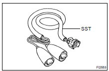
(i) Use SST for the inspection, the injector and the wiring connector test.
SST 09842-30070
8. FUEL SYSTEM
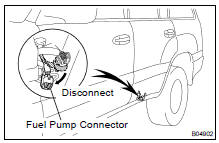
(a) When disconnecting the high fuel pressure line, a large amount of gasoline may be spilled:
- Disconnect the fuel pump connector.
- Start the engine. After the engine has stopped on its own, turn the ignition switch OFF.
- Put a container under the connection.
- Slowly loosen the connection.
- Disconnect the connection.
- Plug the connection with a rubber plug.
- Reconnect the fuel pump connector.
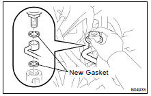
(b) When connecting the union bolt (fuel pressure pulsation damper) on the high pressure pipe union, follow the procedure below:
- Always use 2 new gaskets.
- Tighten the union bolt by hand.
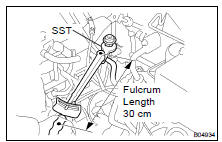
- Using SST, tighten the union bolt to the specified torque.
SST 09612-24014 (09617-24011)
Torque: 33 N·m for use with SST 39 N·m
HINT: Use a torque wrench with a fulcrum length of 30 cm (11.81 in.).

(c) When connecting the flare nut on the high pressure pipe union, follow the procedure below:
- Apply a light coat of engine oil to the flare nut, and tighten the flare nut by hand.
- Using SST, tighten the flare nut to the specified torque.
SST 09023-12700
NOTICE: Do not rotate the fuel filter outlet when tightening the flare nut.
Torque: 34 N·m for use with SST 38 N·m
HINT: Use a torque wrench with a fulcrum length of 30 cm (11.81 in.).
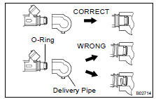
(d) Take following precautions to remove and install the injectors.
- Never reuse the O-ring.
- When placing a new O-ring on the injector, take care not to damage it.
- Coat a new O-ring with spindle oil or gasoline before installing; never use engine, gear or brake oil.
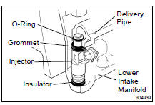
(e) Install the injector to the delivery pipe and lower intake manifold as shown in the illustration.
Before installing the injector, spindle oil or gasoline must be applied on the place where the delivery pipe or the intake manifold touches the O-ring of the injector.
(f) Take following precautions to disconnect the fuel tube connector (quick type):
- Check that there is no dirt on the pipe and around the connector before disconnecting them. If there is, clean the dirt away.

- Be sure to disconnect it with hands.
- Type A: When the connector and the pipe are stuck, push the clicks of the retainer and pull the connector to free to disconnect and pull it out. Do not use any tool at this time.
Type B: When the connector and the pipe are stuck, turn and pull the connector to disconnect. Do not use any tool at this time.
- Inspect if there is any dirt or the likes on the seal surface of the disconnected pipe and clean it away.
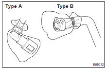
- Prevent the disconnected pipe and connector from damaging and getting foreign objects by covering them with a vinyl bag.
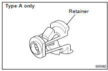
(g) Take following precautions to connect the fuel tube connector (quick type):
- Do not reuse the retainer removed from the pipe.
- Do not use any tool. Use hands to connect the retainer to the pipe.
- Check if there is any damage or foreign objects on the connected part of the pipe.
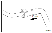
- Match the axis of the connector with that of the pipe, and push in the connector until the connector makes a "click" sound. In the joint part is too tight to connect them, apply a little new engine oil on the tip of the pipe.
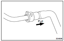
- After finishing the connection, check if the pipe and the connector are securely connected by pulling them.
- Check if there is any fuel leakage.
(h) Take following precautions to handle the nylon tube.
- Pay attention not to turn the joint part of the nylon tube and the quick connector by force when connecting them.
- Pay attention not to twist the nylon tube.
- Do not remove the EPDM protector on the otside of the nylon tube.
- Do not connect them by bending the nylon tube.
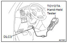
(i) Check that there are no fuel leaks on the fuel system after doing the maintenance.
- Connect the TOYOTA hand-held tester or OBD II scan tool to the DLC3.
- Turn the ignition switch ON and press the TOYOTA hand-held or OBD II scan tool tester main switch ON.
NOTICE: Do not start the engine.
- Select the ACTIVE TEST mode on the TOYOTA hand-held tester or OBD II scan tool .
- Please refer to the TOYOTA hand-held tester or OBD II scan tool operator's manual for further details.
- If you have no TOYOTA hand-held tester or OBD II scan tool, connect the positive (+) and negative (-) leads from the battery to the fuel pump connector (SF-7 ).
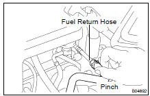
- Pinch the fuel return hose.
The pressure in the high pressure line will rise to approx. 392 kPa (4 kgf/cm2, 57 psi). In this state, check to see that there is no leak on any part of the fuel system.
NOTICE: Always pinch the hose. Do not bend as it may cause the hose to crack.
- Turn the ignition switch OFF.
- Disconnect the TOYOTA hand-held tester from the DLC3.
Test yourself
A quick Toyota Land Cruiser quiz: every answer comes with an explanation and a link to the manual page.