Mono-Motronic Injection System Functional Diagram
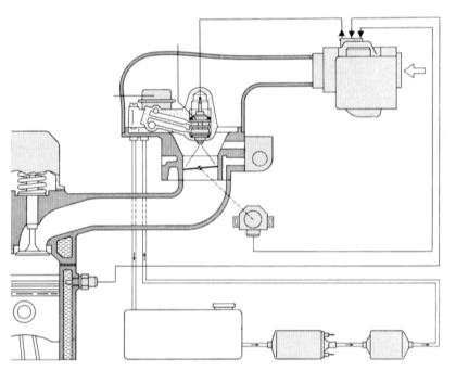
Mono-Motronic Injection System Functional Diagram
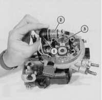
The illustration shows the fuel injector (2) with the connector (1) still attached, removed from its seat (3) in the throttle body. The fuel strainer is visible on the side of the valve.
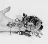
Disassembled fuel pressure regulator:
1 – cover;
2 – spring;
3 – diaphragm;
4 – seat surface.
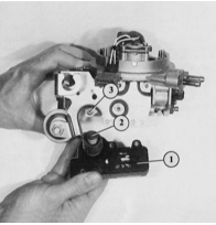
The throttle position potentiometer (1) can be removed separately. This is necessary if the idle switch actuating pin (2) is faulty. Item (3) denotes the throttle stop screw.

The throttle position potentiometer is installed and adjusted at the factory and must not be disassembled. It has been removed only to show the wiper contacts and conductive tracks. If it is faulty, replace the throttle body unit.
Test yourself
A quick Audi 80 quiz: every answer comes with an explanation and a link to the manual page.