Transmission and Final Drive Disassembly
GENERAL INFORMATION
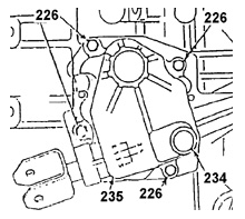
Shift mechanism cover
226. BOLT.
234. PLUG COVER.
235. SHIFT MECHANISM COVER
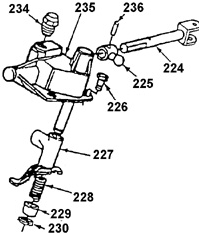
Intermediate shift lever
224. SHAFT WITH FORK
225. BUSHING WITH PIN.
226. BOLT
227. SHIFT INTERMEDIATE LEVER.
228. SPRING.
229. BUSHING.
230. SNAP RING.
234. PLUG COVER.
235. SHIFT MECHANISM COVER.
236. PIN

Installing the auxiliary case in the fixture
44. 5th Speed Shift Fork.
70. INPUT SHAFT GEAR CLUSTER

Removing the 5th gear driven gear
50. SYNCHRONIZER SLEEVE.
60. 5TH GEAR DRIVEN GEAR
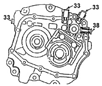
Location of shift rod detent plugs
33. PLUG (21.5 mm)
38. PLUG (50.4 mm)
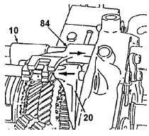
Auxiliary case assembly with shafts and gears
10. 3RD AND 4TH GEAR SHIFT FORK
20. 1st and 2nd Speed Shift Fork.
84. 5TH GEAR SHIFT LEVER
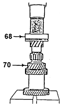
Installing the gear cluster bearing
68. Gear Cluster Bearing.
70. INPUT SHAFT GEAR CLUSTER
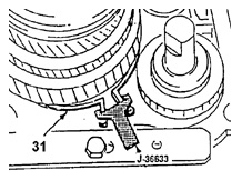
Compressing the snap ring
31. SNAP RING
Remove or disconnect:
PROCEDURE.
1. Remove plug 234 from the shift mechanism cover.
235..
2. Unscrew the cover mounting bolts 226.
235..
2a. Remove cover 235 from case 1.
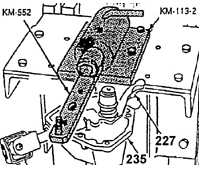
3. Bolt cover 235 to bracket KM-
to bracket KM-
552. Secure the bracket in the
installation fixture KM-113-
2..
4. Shift mechanism cover components:
– snap ring 230.
– bushing 229.
– spring 228.
– intermediate shift lever 227.
– bushing with pin 225 and dowel pin
235..
Warning.
The other parts are non-serviceable and should not be removed from the cover.
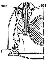
5. Unscrew bolt 103 and remove from the case.
speedometer drive bushing 101.
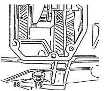
6. Reverse light switch
88..
7. Unscrew bolts 54 and remove case cover 51. Engage 2nd gear.
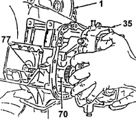
8. Unscrew bolts 65 and separate the
auxiliary case 35 from case 1 and
remove the shafts together with it from the case.
transmission case..
9. Bolt auxiliary case 36 assembly with shafts to bracket KM-
552. Secure bracket KM-552 in installation fixture KM-113-
2.
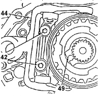
10. Unscrew bolts 42 and remove the
5th gear shift fork.
44.
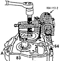
11. Remove 5th gear driven gear 60,
synchronizer sleeve 58 and
5th gear synchronizer hub
56..
Use puller KM-161A. Remove
5th gear needle bearing 81,
ring 61 and both thrust washers
62.
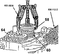
12. Snap ring 63 and the
5th gear drive gear.
64. Place a support under the end of gear cluster 70 before installing the
before installing the
puller.
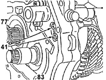
13. Unscrew bolts 41 and remove
5th gear connecting link 46.
together with the pawl
80. Press out
the pin from the connecting link for
pawl replacement.
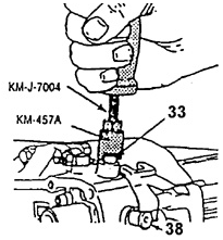
14. Four plugs 33,
38. Use
puller KM-457A and installation
tool KM-J-
7004. Springs
34..
Shift mechanism detent
35..
Pin
39. Interlock mechanism pin.
40..
15. Bolt 79 and support
78. Install the shift rods one at a time in the 2nd,
5th and 3rd gear positions. When 3rd gear is engaged, the interlock is pushed out.
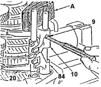
16. Shift fork pins of 3rd/4th gear and
reverse gear. Rest the upper
ends of the shift fork rods on a wooden block.
to prevent damage to the guides
holes in the auxiliary case..
17. Remove the reverse and 3rd/4th gear shift rods and forks from
the auxiliary case. The gear shift sleeves must be in the
neutral position.
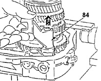
18. Remove the 5th gear shift lever from
the auxiliary case.

19. Remove the snap rings securing the gear block
70 and the output shaft 83 in the
bearing supports of the auxiliary
case. To remove the retaining snap rings 31 and 69, use
snap ring pliers KM-443D..
installation pliers KM-443D..
20. Remove the locking mechanism pin 40 from the hole in the auxiliary case
36.
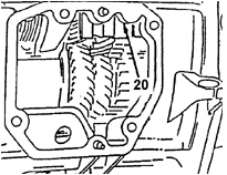
21. Remove the output shaft 83, gear block
input shaft 70, idler gear).
reverse gear 73, fork 20 and rod
21 of 1st and 2nd gear shift from
auxiliary case 36.
22. Clamp the idler gear shaft 72 in a vise using protective
jaw pads. To remove the shaft, lightly tap the auxiliary case with a hammer through a copper drift..
23. Remove the five bolts securing the right cover 126 to the case..
24. Using two screwdrivers, pry the right cover off the case
126..
25. Disassemble the final drive.
– Remove bolts 113 and remove oil pan 112.
– Remove seals 107.
– Mark the relative position of the adjusting nut 109 of the bearing and
case.
– Remove bolt 106 and remove retainer plate 104.
– Remove adjusting nut 109.
– Remove the final drive assembly through the lower opening in the case.
Test yourself
A quick Daewoo Nexia quiz: every answer comes with an explanation and a link to the manual page.