Shift Mechanism Linkage Adjustment
GENERAL INFORMATION
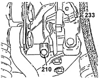
Location of the clamp bolt
210. CLAMP BOLT
239. LEVER PIVOT PIN
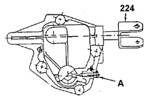
Location of the adjustment hole plug
A. PLUG
224. SHAFT WITH FORK
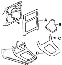
Installing the shift lever boot. A. CONTROL PANEL TRIM
B. BOOT
C. SCREW
D. CENTER CONSOLE TRIM
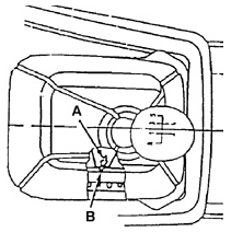
Shift lever position when adjusting the linkage. A. POINTER
B. MARK
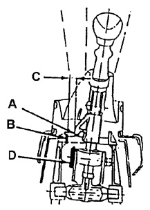
Measuring the adjustment clearance. A. PAWL
B. STOP
C. CLEARANCE
D. ADJUSTING NUT
PROCEDURE.
1. Disconnect the negative battery cable.
2. Move shift lever 203 to the neutral position.
3. Loosen clamp bolt 210.
4. Remove the plug from the adjustment hole in mechanism cover 235.
Turn fork 224 so that a
4.76 mm diameter pin can be inserted through the adjustment hole into the hole in the intermediate lever.
switch
227..
5. Remove boot 202 and pull it upward to access the mechanism.
6. Move shift lever 203 to the 1st or 2nd gear position.
6a. Align the pointer with the mark and tighten the bolt.
210..
6b. Tighten the bolt to 14 N·m.
6c. After tightening to the specified torque, tighten the bolt an additional 90–180 degrees.
7. Move the shift lever to the neutral position and check the clearance
between pawl A and stop B. After adjustment, the clearance must be 3 mm.
8. Remove the 4.76 mm diameter pins from the holes and install the plug.
9. Adjust clearance C using nut D, as shown in the figure. Measuring the adjustment clearance. Before adjusting, bend back the two locking tabs of the nut.
9a. The clearance must be 11.6 ± 0.2 mm.
9b. Bend the locking tabs over the adjusting nut to prevent it from loosening.
10. Install boot 202 and the center console trim.
Warning.
All gears must engage easily with the vehicle stationary, the engine running at idle, and the clutch disengaged.
Test yourself
A quick Daewoo Nexia quiz: every answer comes with an explanation and a link to the manual page.