Transaxle Assembly
GENERAL INFORMATION
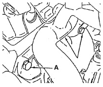
Transaxle-to-engine mounting bolt A. BOLT
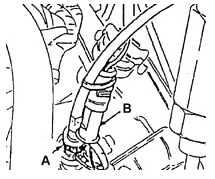
Location of vehicle speed sensor
A. SPEEDOMETER DRIVE CABLE.
B. VEHICLE SPEED SENSOR ELECTRICAL CONNECTOR
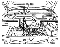
Engine support crossmember
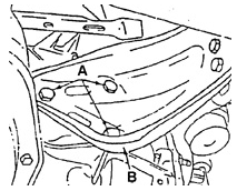
Left bracket A. ENGINE-TO-BRACKET MOUNTING BOLTS.
B. BRACKET
Remove or disconnect
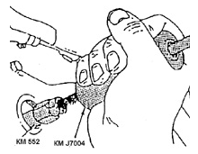
Transmission Input Shaft Removal
PROCEDURE.
1. Disconnect the negative battery cable.
2. Air cleaner.
3. Clutch cable and clutch release lever.
4. Retainer 223 and pin 237 of the gear shift control universal joint.
5. Speedometer drive cable, vehicle speed sensor connector and
reverse light switch connector.
6. Loosen clamp bolt 210.
7. Remove the three upper transaxle-to-engine bolts.
8. Install the engine support crossmember.
9. Raise the vehicle.
10. Remove the front wheels.
11. Splash shield.
12. Disconnect the capacitor wire (electromagnetic interference suppression)
from the transaxle case.
13. Press both ball joints out of the steering knuckles.
14. Axle shafts.
15. Transaxle case cover.
16. Disconnect the axle shafts from the transaxle.
17. Mark the installation position of the input shaft relative to the gear
assembly with paint for ease of subsequent installation.
18. Pull out the input shaft, remove the support.
19. Support the power unit.
20. Remove the left front, then the left rear engine brackets, and unscrew the lower transaxle case mounting bolts.
21. Move the transaxle aside and remove it.
Install or connect
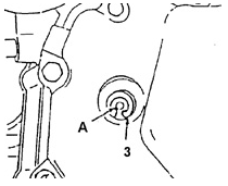
Installing the snap ring on the end of the input shaft A. SNAP RING
3. INPUT SHAFT SNAP RING
PROCEDURE.
1. Before installing the transaxle, install the right axle shaft in place, since its
installation will be impossible later (after the transaxle is connected to the engine).
2. Screw in the lower transaxle case-to-engine bolts and tighten them to the specified torque. Bolt tightening torque 60 N·m.
3. Install the left rear bracket bolts. Tighten the engine-to-bracket mounting bolts to torque 90 N·m.
4. Install the left front bracket and bolts. Tighten the front bracket-to-transaxle case mounting bolts to torque 60 N·m. Tighten the bracket-to-support mounting
bolts to torque 60 N·m.
5. Leave both axle shafts in the transaxle case.
6. Connect the steering tie rod ball joints and secure them.
7. Carefully insert the input shaft into the splined holes of the gear assembly and
clutch driven disc. To return the shaft to its original position relative to mating parts, align it with the mark made before disassembly.
8. Screw the bolt into the input shaft
67. Tighten the input shaft bolt to torque 15 N·m.
9. Snap ring
66..
10. Ground cable to the case cover, plug 53 and the capacitor wire (electromagnetic interference suppression).
electromagnetic interference suppression.
11. Install the flywheel cover and screw in the bolts. Tighten the flywheel cover bolts to torque 7 N·m.
12. Screw in the upper transaxle-to-engine bolt. Tighten the upper transaxle case-to-engine bolt to torque 60 N·m.
13. Splash shield.
14. Install both front wheels and lower the vehicle. Tighten the wheel bolts.
to torque 90 N·m..
15. Connect the wiring to the reverse light switch and the drive cable.
speedometer..
16. Connect the clutch release cable and adjust the drive..
17. Negative battery cable..
Inspection
PROCEDURE.
Transmission oil level.
Transmission fill capacity 1.8 L. Use manual transmission oil.
transmission oil of the DEUTSCH VEEDOL HD T/M FLUID, SAE 80 brand.
Test yourself
A quick Daewoo Nexia quiz: every answer comes with an explanation and a link to the manual page.