Cylinder Head. Disassembly and Assembly of Sub-Systems
Special Service Tools / General Equipment
 |
303-1249 Valve Spring Compressor TKIT-2006UF-FLM TKIT-2006UF-ROW |
 |
303-300 (T87C-6565-A) Kit, Valve Spring Compressor TKIT-1988-FESTIVA T88C-1000-ST TKIT-1988-TRACER TKIT-2009TC-F |
 |
303-350 (T89P-6565-A) Compressor, Valve Spring TKIT-1990-LMX TKIT-1989-F TKIT-1989-FM TKIT-1989-FLM |
 |
303-472 (T94P-6565-AX) Adapter, Valve Spring Compressor TKIT-1994-LMH/MH2 TKIT-1994-FX/FMX/FLMX |
| Feeler gauge | |
| Wood block | |
Materials
| Name | Specification |
|---|---|
| Motorcraft® Multi-Purpose Spray Lubricant XL-5-A |
ESB-M1C93-B |
| Engine Oil — SAE 5W-20 — Semi-Synthetic Engine Oil XO-5W20-Q1SP |
WSS-M2C945-B1 |
| Motorcraft® Threadlocker 262 TA-26 |
WSK-M2G351-A6 |
| Engine Oil — SAE 5W-20 — Semi-Synthetic Engine Oil XO-5W20-Q1SP |
WSS-M2C945-B1 |
DISASSEMBLY
NOTICE: When performing engine repairs, cleanliness is extremely important. Any foreign material, including any material created during the cleaning of gasket surfaces, that enters the oil passages, coolant passages or oil pan may cause engine failure.
- Loosen the camshaft bearing caps one turn at a time until all tension is released from the camshaft bearing caps. Remove the bolts, camshaft caps and camshafts.
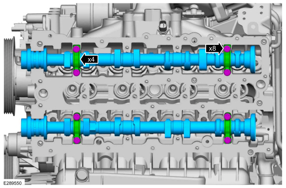
- Remove the valve lifters.

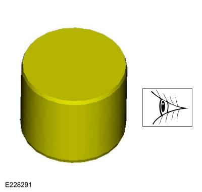
- Inspect the valve lifters.
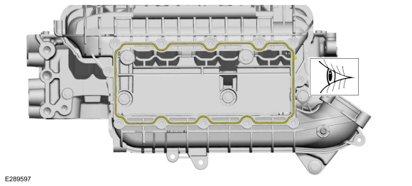
- Remove the bolts, studs and CAC.

- Inspect the CAC gasket.
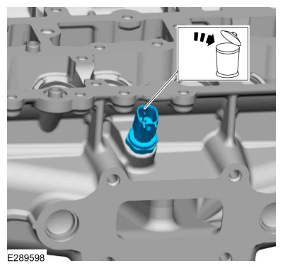
- Unscrew the bolts and remove the intake manifold.

- Remove and discard the CHT sensor.
- Remove the bolt and bracket.
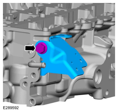
- Remove the cylinder head plug and discard it.
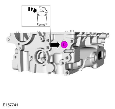
NOTICE: Use only hand tools when removing or installing the spark plug, otherwise damage to the cylinder head or spark plug may occur.
NOTICE: Dropping a spark plug may cause internal damage to it. If dropped, the spark plug must be discarded. Using a damaged spark plug may cause cylinder misfire, which can result in engine damage.
Remove the spark plugs.
- Using the special tools, remove the valve keepers, valve spring retainers and valve springs.
Use special service tools: 303-300 (T87C-6565-A) Valve Spring Compressor Kit, 303-350 (T89P-6565-A) Valve Spring Compressor, 303-472 (T94P-6565-AX) Valve Spring Compressor Adapter, 303-1249 Valve Spring Compressor.
Material: Motorcraft® Multi-Purpose Spray Lubricant / XL-5-A (ESB-M1C93-B)
- Inspect and install new components as necessary.

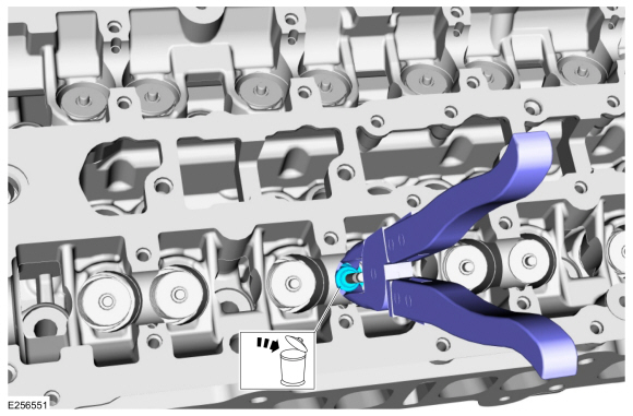
- Use commercially available pliers to remove the valve stem seal.
- Discard the valve stem seal.
- Remove the intake and exhaust valves.

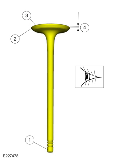
- Valve stem end for grooves or chamfer.
- Valve face and margin for pits, grooves or scratches.
- Valve head for signs of burning, erosion, warping and cracking.
- Valve margin for wear.
ASSEMBLY
- Lubricate and install the intake and exhaust valves.
Material: Engine Oil - SAE 5W-20 - Synthetic Engine Oil / XO-5W20-Q1SP (WSS-M2C945-B1)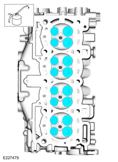
- Lubricate the valve stem seal with clean engine oil.
Material: Engine Oil - SAE 5W-20 - Synthetic Engine Oil / XO-5W20-Q1SP (WSS-M2C945-B1)
- Using commercially available valve stem seal pliers, install the valve stem seal.

- Lubricate the valve stem seal with clean engine oil.
- Using the special tools, install the valve springs, valve spring retainers and valve keepers.
Use special service tools: 303-300 (T87C-6565-A) Valve Spring Compressor Kit, 303-350 (T89P-6565-A) Valve Spring Compressor, 303-472 (T94P-6565-AX) Valve Spring Compressor Adapter, 303-1249 Valve Spring Compressor.
Material: Motorcraft® Multi-Purpose Spray Lubricant / XL-5-A (ESB-M1C93-B)
NOTICE: Use only hand tools when removing or installing the spark plug, otherwise damage to the cylinder head or spark plug may occur.
Install the spark plugs.
Torque: 115 lb-in (13 N·m)
- Install the cylinder head plug.
Torque: 21 lb-ft (29 N·m)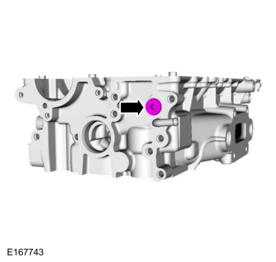
- Install the bracket and bolt.
Torque: 17 lb-ft (23 N·m)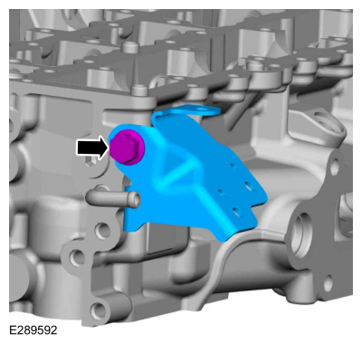
- Install a new CHT sensor.
Torque: 89 lb-in (10 N·m)
- Visually inspect the intake manifold gasket for dents, cuts, and scratches. If these conditions are not present, the gaskets may be reused.

- Install the intake manifold and tighten the bolts in the sequence shown.
Material: Motorcraft® Threadlock 262 / TA-26 (WCK-M2G351-A6)
Torque:
Step 1: Tighten bolts 1 and 2 to: 18 lb-in (2 N·m)
Step 2: Tighten bolts 3 and 4 to: 18 lb-in (2 N·m)
Step 3: Tighten bolts 1 and 2 to: 159 lb-in (18 N·m)
Step 4: Tighten bolts 3, 4, 5 and 6 to: 89 lb-in (10 N·m)
Step 5: Tighten bolts 1 and 2 to: 159 lb-in (18 N·m)
Step 6: Tighten bolts 3, 4, 5 and 6 to: 89 lb-in (10 N·m)
- Make sure the CAC seal remains correctly positioned.
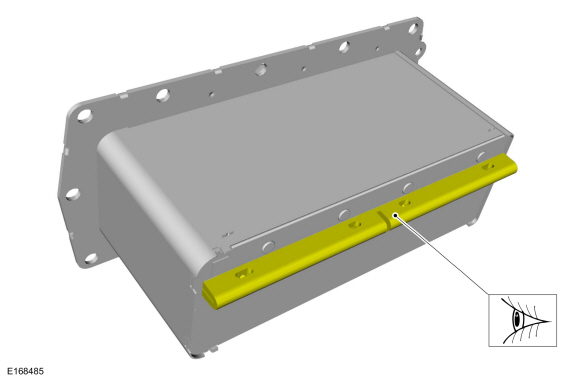
- Install the CAC, bolts and studs.
- Hand-tighten bolts 7 and 10.
- Hand-tighten the remaining bolts.
- Tighten the bolts and studs.
Torque: 89 lb-in (10 N·m)
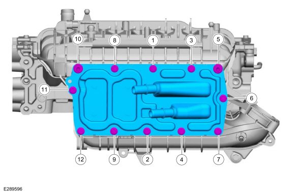
- Lubricate with clean engine oil and install the valve lifters.
Material: Engine Oil - SAE 5W-20 - Synthetic Engine Oil / XO-5W20-Q1SP (WSS-M2C945-B1)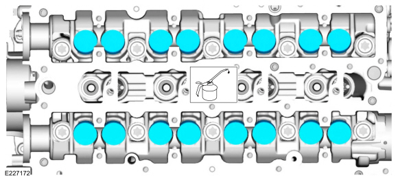
NOTICE: If the cylinder head is not installed on wooden blocks, damage to the cylinder head may occur.
Install the cylinder head on wooden blocks.
Use common equipment: wooden blockNOTICE: Failure to follow the camshaft tightening procedure may damage the camshafts.
NOTICE: Make sure the camshafts and camshaft bearing caps are installed in their original positions or engine damage may occur.
- Evenly tighten the bolts, half a turn at a time, until the camshaft bearing caps and VCT bridge are seated on the cylinder head.
Material: Engine Oil - SAE 5W-20 - Synthetic Engine Oil / XO-5W20-Q1SP (WSS-M2C945-B1)
Torque:
Step 1: Tighten bolts 1 through 16 to: 62 lb-in (7 N·m)
Step 2: Tighten bolts 17 through 20 to: 89 lb-in (10 N·m)
Step 3: Tighten bolts 1 through 16 an additional: 45°
Step 4: Tighten bolts 17 and 18 an additional: 70°
Step 5: Tighten bolts 19 and 20 an additional: 53°
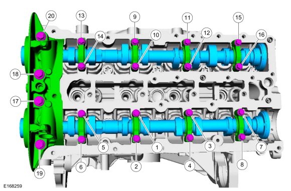
- Evenly tighten the bolts, half a turn at a time, until the camshaft bearing caps and VCT bridge are seated on the cylinder head.
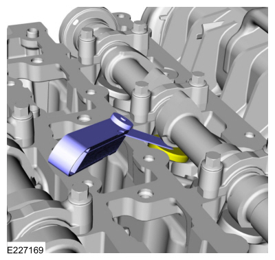
- Using the camshaft flats, rotate the camshaft to place the cam lobe on the base circle so that the lobe points away from the tappet.
- Using a feeler gauge, measure the clearance of each valve and record its position.
Use general equipment: Feeler Gauge
- Repeat to measure all cam/tappet clearances.
NOTICE: Failure to follow the camshaft loosening procedure may damage the camshafts.
- Loosen the camshaft bearing caps 2 turns at a time until all tension is released from the camshaft bearing caps in the sequence shown.
- Remove the bolts and the camshaft caps.
- Remove the camshafts.
- Discard the bolts.

Test yourself
A quick Ford Fusion quiz: every answer comes with an explanation and a link to the manual page.