Powertrain
Valve Cover - Removal and Installation
In this manual: Powertrain
22steps
~132min
4/5difficulty
Done 0 of 22
Special Service Tools / General Equipment
Hose Clamp Removal/Installation Tool
Materials
| Name | Specification |
|---|---|
| Flange Sealant CU7Z-19B508-A |
WSS-M2G348-A11 |
| Motorcraft® Metal Surface Preparation Wipes ZC-31-B |
- |
| Engine Oil — SAE 5W-20 — Semi-Synthetic Engine Oil XO-5W20-Q1SP |
WSS-M2C945-B1 |
Removal
- Release the fuel system pressure.
Refer to: Fuel System Pressure Release (310-00A Fuel System — General Information — 1.5 L EcoBoost (118 kW/160 L PS) — I4, General Procedures). - Remove the engine appearance cover.
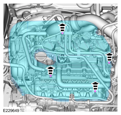
- Disconnect the EVAP canister purge valve tubes from the TC intake pipe.
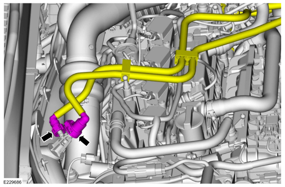
- Remove the oil level indicator.
- Disconnect the couplings and remove the hose.
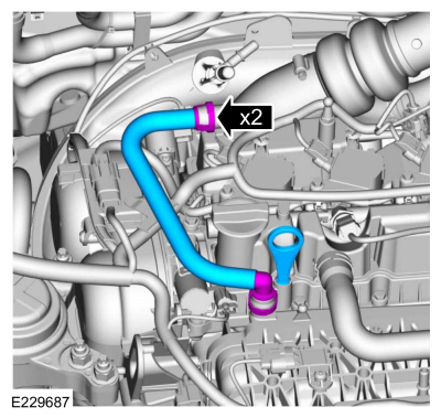
- Disconnect the harness retainer from the hose.
- Release the clamps and move the hoses aside.
Use common service equipment: hose clamp removal and installation tool.
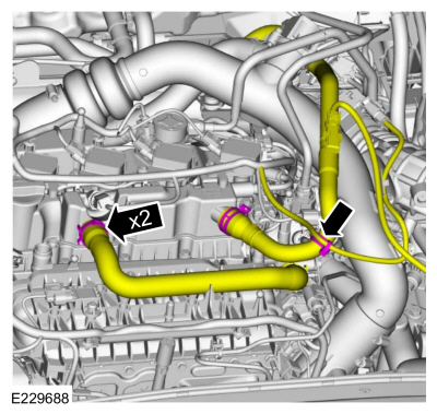
- Remove the fuel rail.
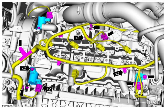
Refer to: Fuel Rail (303-04A Fuel Charging and Controls — 1.5 L EcoBoost (118 kW/160 L PS) — I4, Removal and Installation). - Disconnect the harness retainers and disconnect the harness electrical connectors.
- Remove the bolts and the VCT oil control solenoids.
- Remove the bolt and the intake CMP sensor.
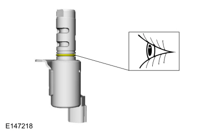
- Inspect the O-ring of the VCT oil control solenoid.
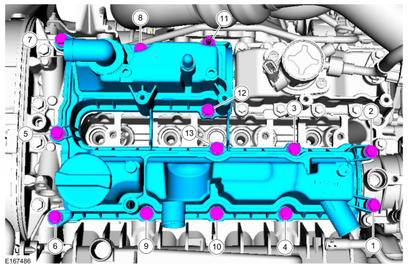
- Remove the bolts in the sequence shown and remove the valve cover.
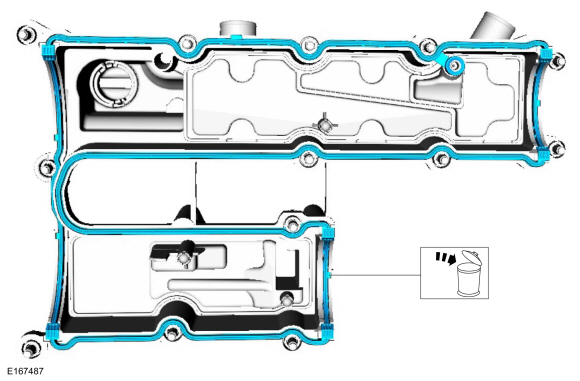
- Remove and discard the valve cover gasket.
Installation
NOTICE: Do not use metal scrapers, wire brushes, power abrasive discs or other abrasive means to clean sealing surfaces. These tools leave scratches and gouges that create leak paths.
Make sure the mating surfaces are clean and free of foreign material.
Material: Motorcraft® Metal Surface Preparation Wipes / ZC-31-B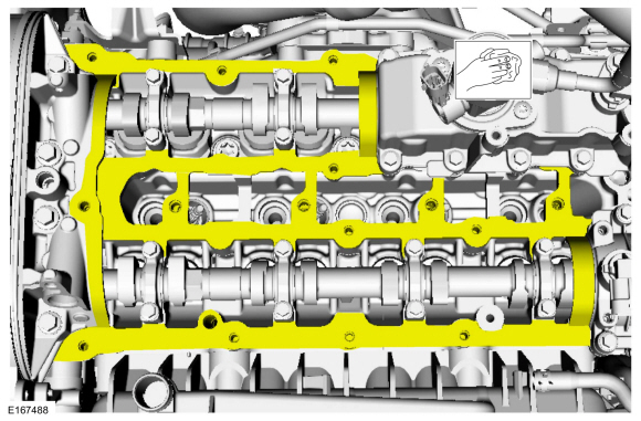
- Install a new valve cover gasket.
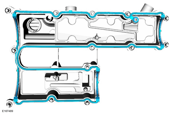
- Apply 1.5 mm (0.059 in) diameter beads of sealant as shown in the illustration.
Material: Flange Sealant / CU7Z-19B508-A (WSS-M2G348-A11)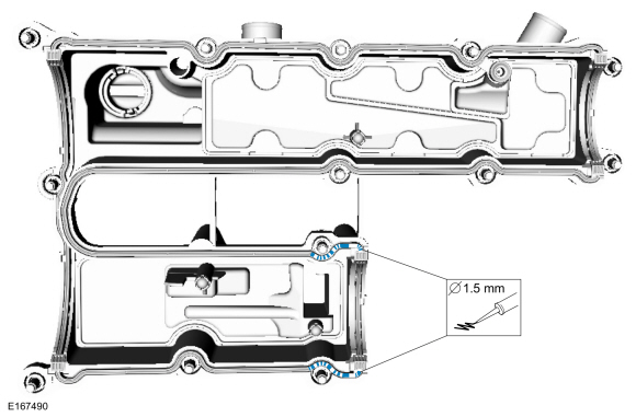
- Apply 1.5 mm (0.059 in) diameter beads of sealant as shown in the illustration.
Material: Flange Sealant / CU7Z-19B508-A (WSS-M2G348-A11)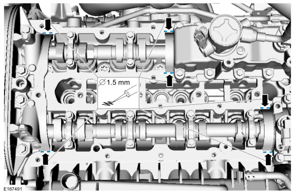
- Install the valve cover and bolts in the sequence shown in 3 stages.
Torque:
Stage 1: 44 lb-in (5 N·m)
Stage 2: 80 lb-in (9 N·m)
Stage 3: 89 lb-in (10 N·m)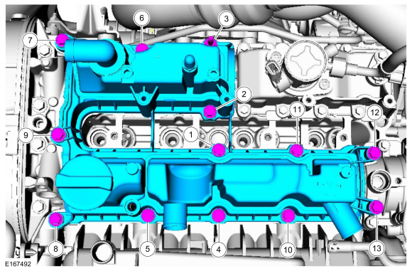
- Lubricate the O-ring of the VCT oil control solenoid.
Material: Engine Oil - SAE 5W-20 - Synthetic Engine Oil / XO-5W20-Q1SP (WSS-M2C945-B1)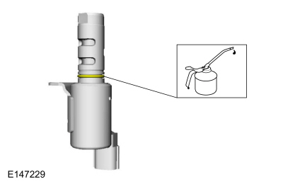
- Install the intake CMP sensor and bolt.
Torque: 80 lb-in (9 N·m)
- Install the VCT oil control solenoids and bolts.
Torque: 71 lb-in (8 N·m)
- Install the harness retainers and connect the harness electrical connectors.
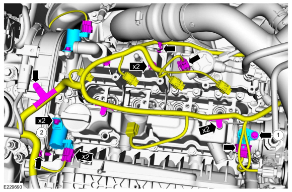
- Install the intake CMP sensor and bolt.
- Install the fuel rail.
Refer to: Fuel Rail (303-04A Fuel Charging and Controls — 1.5 L EcoBoost (118 kW/160 L PS) — I4, Removal and Installation). - Position the hoses and loosen the clamps.
Use common service equipment: hose clamp removal and installation tool.
- Attach the harness retainer to the hose.
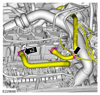
- Position the hoses and loosen the clamps.
- Install the hose and connect the couplings.
- Install the oil level indicator.
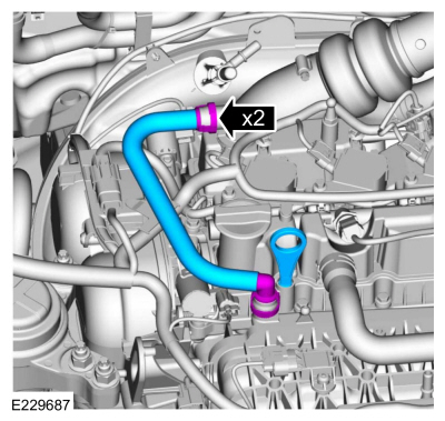
- Connect the EVAP canister purge valve tubes to the TC inlet pipe.
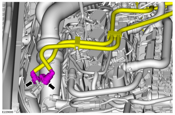
- Install the engine outer cover.

Test yourself
A quick Ford Fusion quiz: every answer comes with an explanation and a link to the manual page.
Was this page helpful?