Engine - Disassembly
Special Service Tools / General Equipment
 |
100-001 (T50T-100-A) Slide hammer |
 |
300-OTC1819E Floor Crane 2200 lb, Folding |
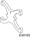 |
303-1097 Locking Tool, Variable Camshaft Timing Oil Control Valve TKIT-2010B-FLM TKIT-2010B-RYAD |
 |
303-1502 Engine Lifting Device TKIT-2012A-FL TKIT-2012A-RYAD |
 |
303-409 (T92C-6700-CH) Remover, Crankshaft Seal TKIT-1992-FX/FMX/FLMX TKIT-1993-LMX/MX |
 |
303-748 Crankshaft Locking Tool TKIT-2010B-FLM TKIT-2010B-RHD |
 |
307-005 (T59L-100-B) Slide Hammer |
 |
308-375 Remover, Input Shaft Seal TKIT-2005U-M TKIT-1999-F/FLM/LT |
 |
310-206 Puller, Fuel Injector TKIT-2009A-FLM |
| Heat gun | |
| Hose Clamp Removal/Installation Tool | |
Materials
| Name | Specification |
|---|---|
| Motorcraft® Brake Parts Cleaner PM-4-A, PM-4-B |
- |
NOTICE: Do not loosen or remove the crankshaft pulley bolt without first installing the special service tools. The crankshaft pulley and the crankshaft timing sprocket are not connected to the crankshaft. Before any repair that requires loosening or removing the crankshaft pulley bolt, the crankshaft and camshafts must be locked with the special service tools, otherwise serious engine damage may occur.
NOTICE: Cleanliness is extremely important when repairing the engine. Any foreign material, including material created during the cleaning of gasket surfaces, that enters the oil passages, coolant passages or oil pan may cause engine failure.
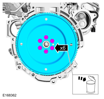
- Remove the bolts and the flexplate. Discard the bolts.
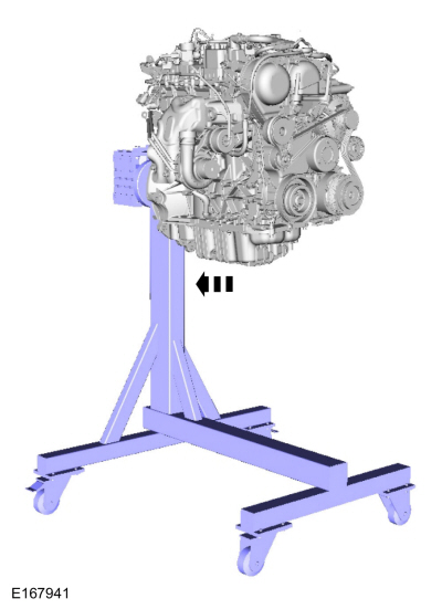
- Install the engine on the engine stand.
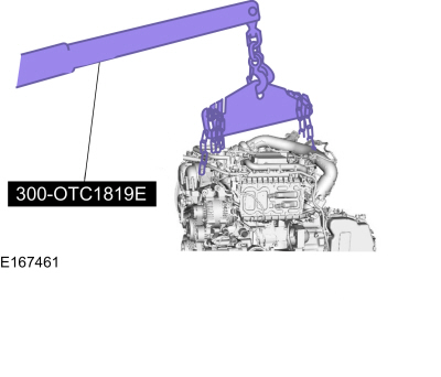
- Remove the special service tool: 300-OTC1819E 2200 lb Floor Crane, Folding.
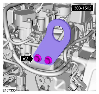
- Remove the special service tool: 303-1502 Engine Lifting Device.
- Remove the coolant hose.
Special Service Tool: Hose clamp removal/installation tool.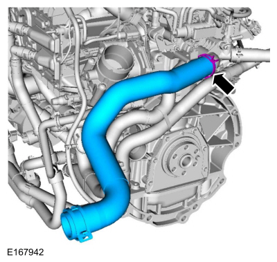
- Remove the coolant hose.
Special Service Tool: Hose clamp removal/installation tool.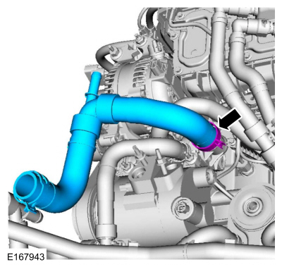
- Disconnect the harness retainer and disconnect the electrical connector.
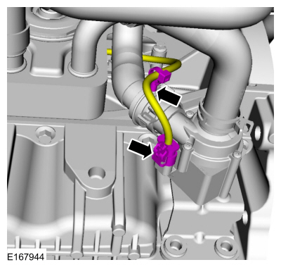
- Disconnect all coolant hoses.
Special Service Tool: Hose clamp removal/installation tool.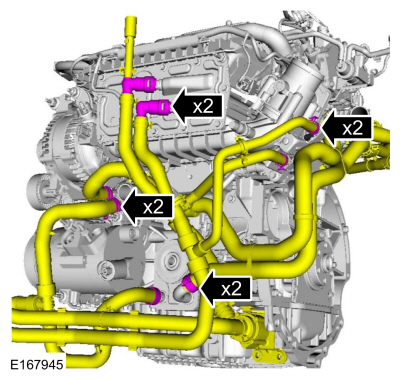
- Remove the coolant hoses.
Use common service equipment: hose clamp removal/installation tool.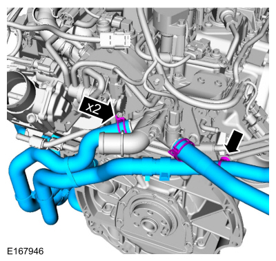
- Disconnect the PCV hose quick connectors and remove the hoses.
Special Service Tool: Hose clamp removal/installation tool.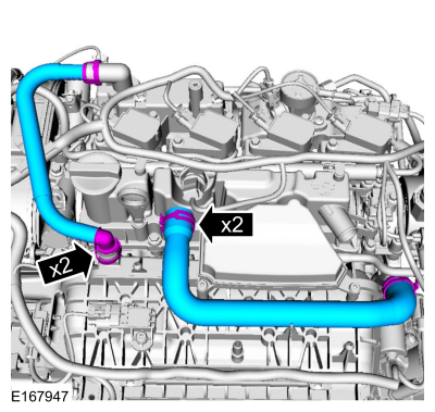
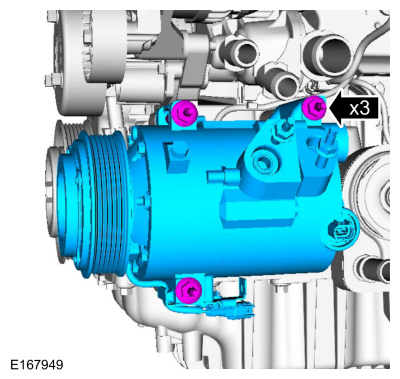
- Remove the bolts and the A/C compressor.
- Remove the bolts and the bracket.
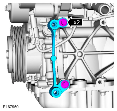
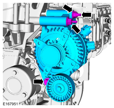
- Remove the nut, stud, stud and alternator.
- Remove the bolt and the accessory drive belt tensioner pulley.
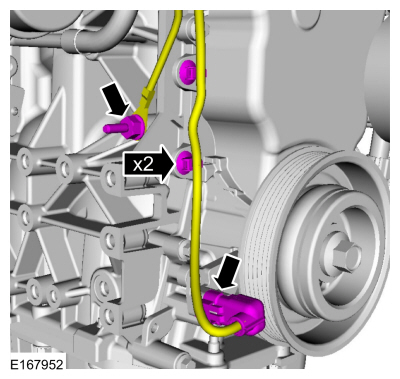
- Disconnect the retainers and disconnect the crankshaft position sensor electrical connector.
- Remove the stud and set the wiring harness aside.
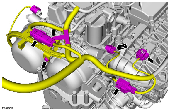
- Disconnect the harness retainer and remove the clip.
- Disconnect the electrical connectors and set the wiring harness aside.
- Disconnect the wiring harness retainers and disconnect the electrical connectors.
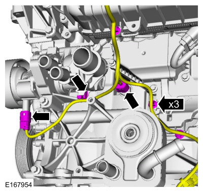
- Disconnect the wiring harness retainers and disconnect the electrical connectors.
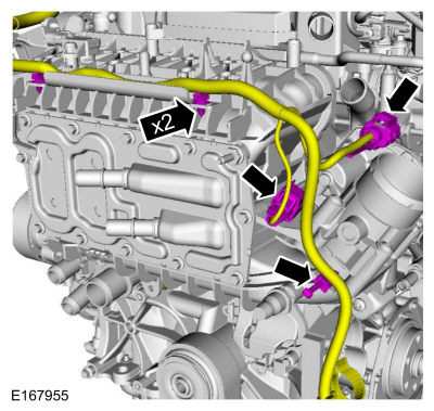
- Disconnect the wiring harness retainers and disconnect the electrical connectors.
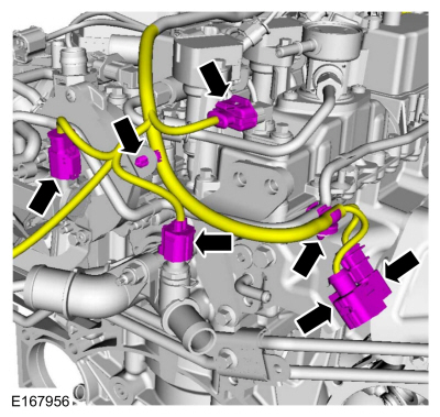
- Position the cover and disconnect the CHT sensor harness electrical connector.
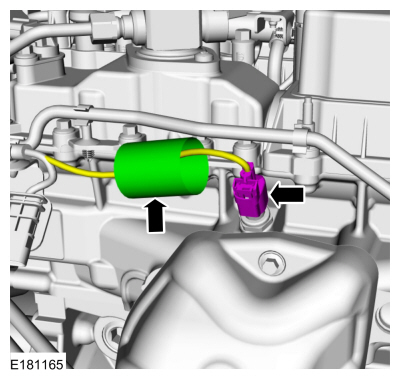
- Disconnect the retainers, disconnect the electrical connectors and remove the harness.
- Remove the oil level indicator.
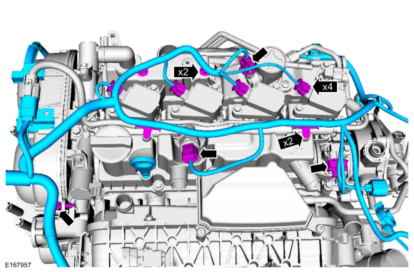
- Disconnect the vacuum hose and bracket.
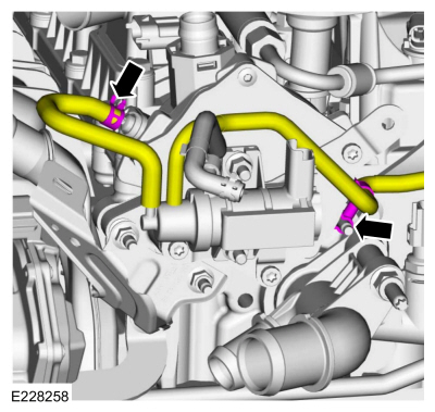
- Remove the nut and the coolant outlet. Discard the nut.
- Remove the retainers and set the vacuum hose aside.
- Remove the nuts, bolt and brackets.
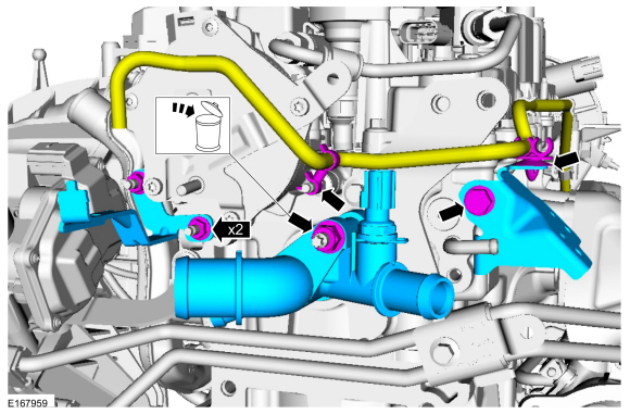
- Inspect the coolant outlet O-ring.
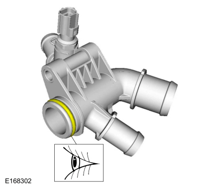
- Remove the studs and the vacuum pump. Discard the studs.
- Remove the bolts and the engine lift bracket.
- Remove the bolt and stud.
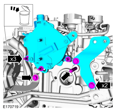
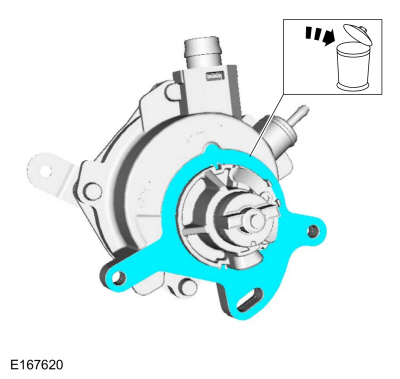
- Remove and discard the vacuum pump gasket.
- Disconnect the retainers and remove the TC wastegate control hose.
- Remove the nut, bolt and bracket.
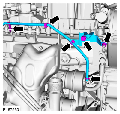
- Remove the retainers and set the TC coolant tube aside.
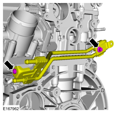
- Remove the retainers and the TC coolant tube.
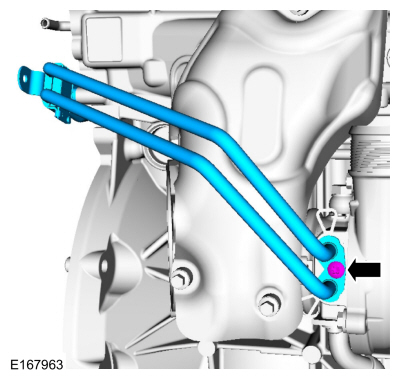
NOTICE: Do not use a wire brush; damage to the sealing area will cause leaks.
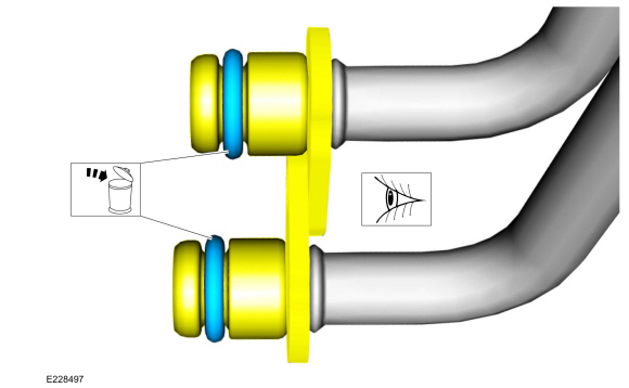
Inspect the turbocharger tube and sealing surfaces. Make sure the retaining clip is not bent. Check the squareness of the retaining clip in the area of the O-ring. Use brake cleaner and a nylon brush.
- Remove and discard the TC coolant tube O-rings.
Material: Motorcraft® Metal Brake Parts Cleaner / ESR-M14P4-A, ESR-M14P4-B
- Remove the bolts, stud and CAC.
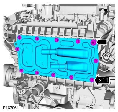
- Remove the bolts and the intake manifold.
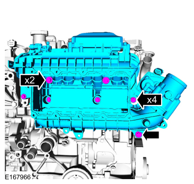
- Remove the bolts and the VCT oil control solenoids.
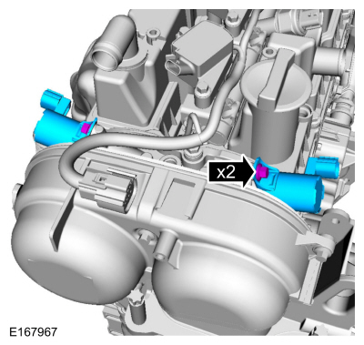
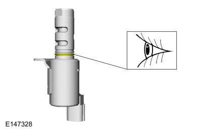
- Inspect the O-ring of the VCT oil control solenoid.
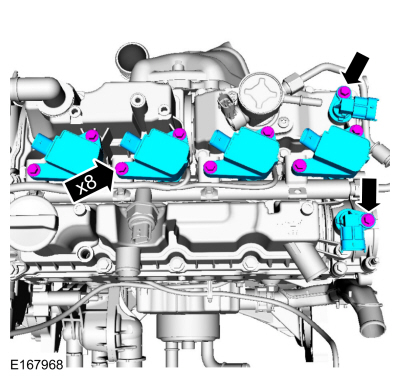
- Remove the bolts and the ignition coil-on-plug.
- Remove the bolts and the CMP sensors.
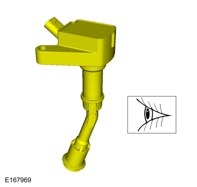
- Inspect the coil on the plug.
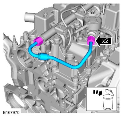
- Loosen the flare nuts, then remove and discard the high-pressure fuel line.
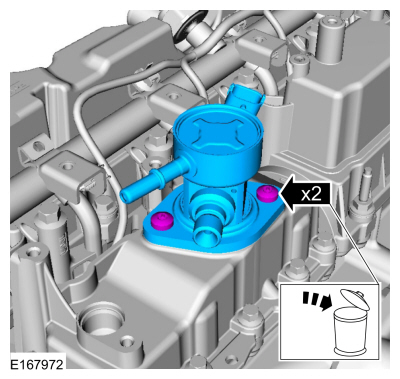
- Remove the retainers and the high-pressure fuel pump. Discard the retainers.
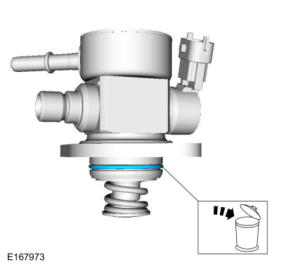
- Remove and discard the high-pressure fuel pump O-ring.
- Remove the high-pressure fuel pump tappet.
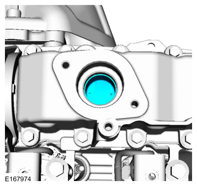
- Inspect the high-pressure fuel pump tappet.
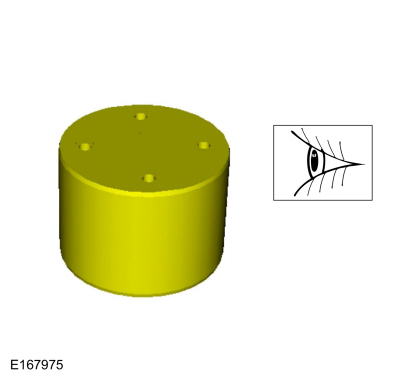
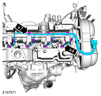
- Disconnect the electrical connectors and remove the harness.
NOTICE: Pull the fuel rails in the direction of the fuel injector axis, otherwise the injectors may be damaged.
Remove the bolts and the fuel rail assembly.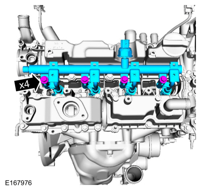
- Remove the clip and all fuel injectors remaining in the fuel rail.
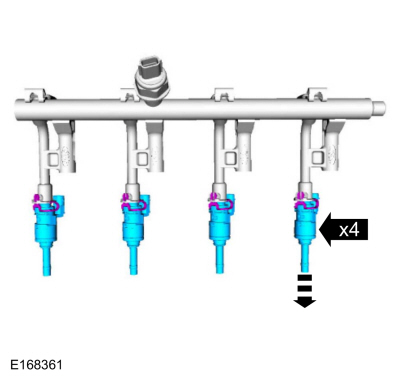
- Remove and discard the fuel injector clamp.
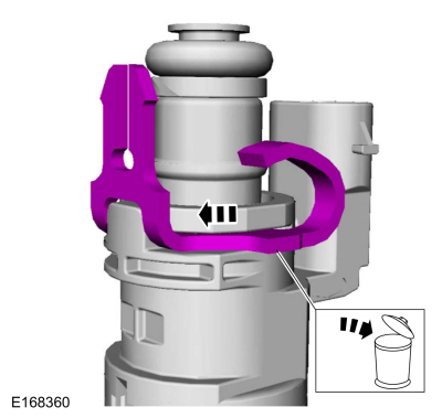
- Using special tools, remove the fuel injector.
Special Service Tools: 307-005 (T59L-100-B) Slide hammer, 310-206 Fuel injector puller.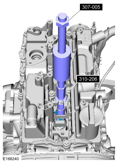
NOTICE: Do not place the valve cover sealing surface on a bench, as the check valve and divider leg may break.
Loosen the bolts in the sequence shown and remove the valve cover.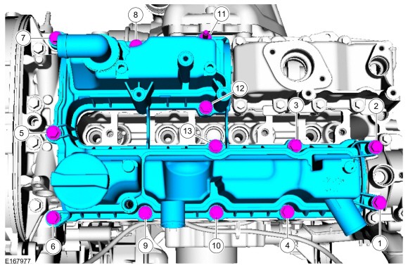
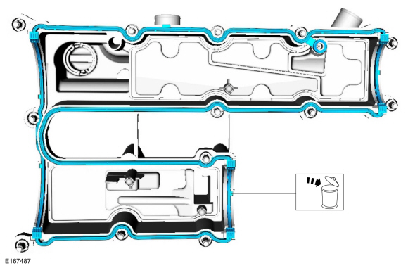
- Remove and discard the valve cover gasket.
NOTICE: Use a heat gun to soften the flange sealant to assist in removing the fuel pump mounting bracket. Failure to follow these instructions may damage the fuel pump mounting bracket.
- Remove the bolts in the sequence shown, heat and break the adhesive bond, and remove the high-pressure fuel pump drive unit.
Required Equipment: Heat gun.
- Remove and discard the O-ring.
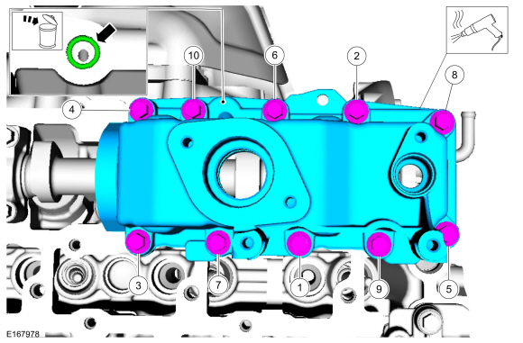
- Remove the bolts in the sequence shown, heat and break the adhesive bond, and remove the high-pressure fuel pump drive unit.
NOTICE: Use a heat gun to soften the flange sealant to assist in removing the fuel pump mounting bracket. Failure to follow these instructions may damage the fuel pump mounting bracket.
- Remove the engine cover stud.
- Remove the bolts and the stud.
- Heat and break the adhesive bond, remove the brake vacuum pump cover.
Use common equipment: heat gun.
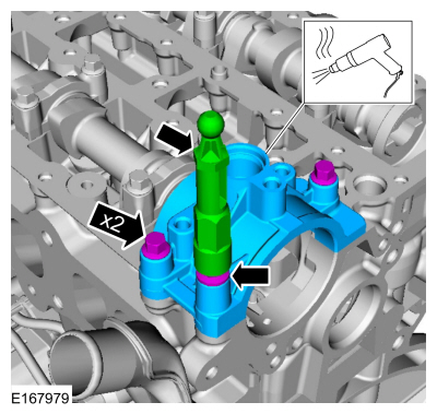
- Remove the clip and the oil cooler. Discard the clip.
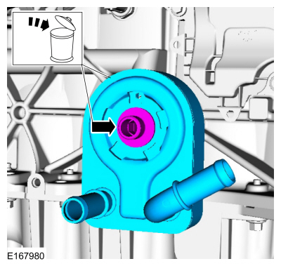
- Disconnect the retainer, remove the bolts and the CKP sensor.
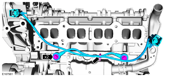
- Remove the bolt, disconnect the quick connector and remove the PCV oil separator inlet pipe.
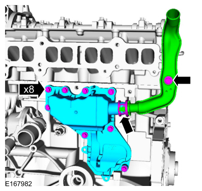
- Remove the bolts and the crankcase vent oil separator.
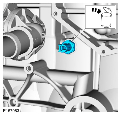
- Remove and discard the oil pressure sensor.
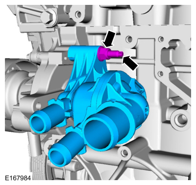
- Remove the nut, stud and thermostat housing.
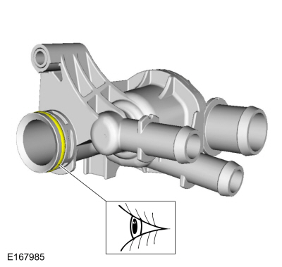
- Inspect the thermostat housing O-ring.
- Remove the bolts and the TC heat shield.
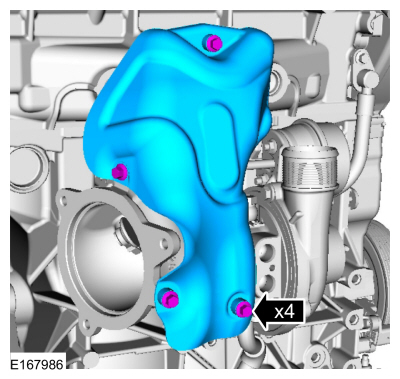
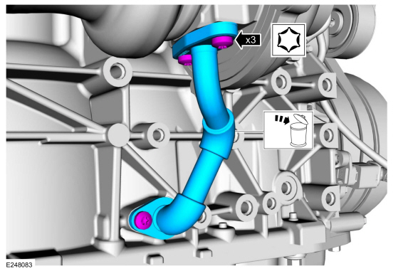
- Remove the TC oil return tube with the TC bolts.
- Remove the TC oil return tube from the cylinder block bolt, then remove and discard the TC oil return tube.
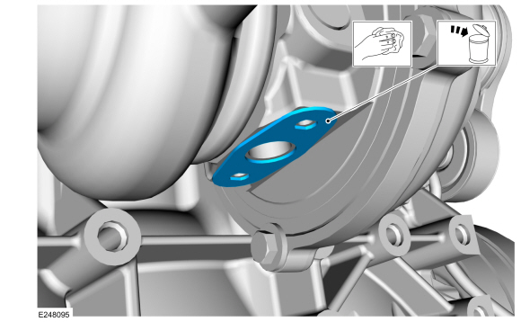
- Remove and discard the TC oil return tube gasket. Clean the sealing surface.
- Remove the nuts, retainer and TC. Discard the nuts.
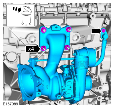
- Remove and discard the TC oil supply tube assembly, including the bolt, sealing washers and O-rings.
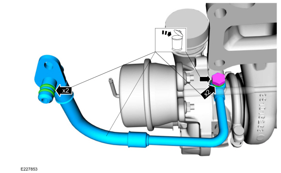
- Remove and discard the TC mounting gasket and studs.
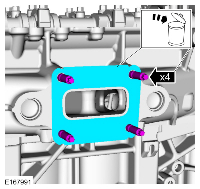
- If equipped with a block heater, remove the nut and the block heater.
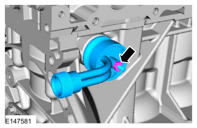
- Remove the stud and set the front engine cover cap aside.
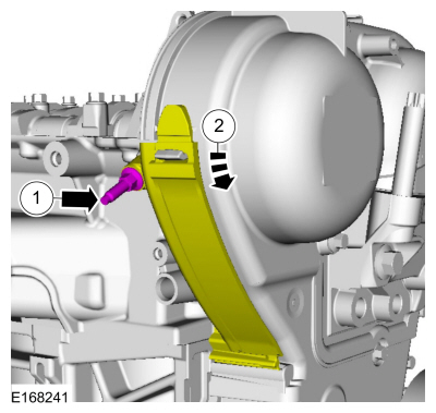
- Remove the coolant pump bolts and pulley.
- Remove the engine mount stud.
- Remove the engine front cover bolts.
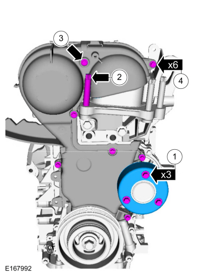
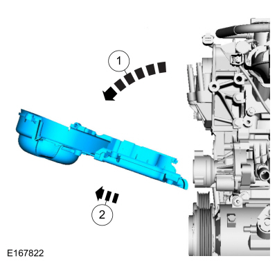
- Remove the engine front cover.
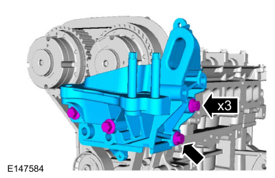
- Remove the bolts and the engine mount bracket.
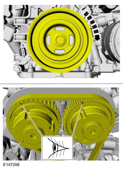
- Rotate the crankshaft pulley until the timing marks are at the 11 o'clock position.
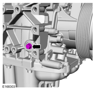
- Remove the engine plug bolt.
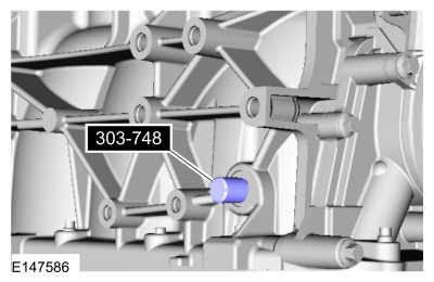
- Install the special service tool: 303-748 Crankshaft Locking Tool.
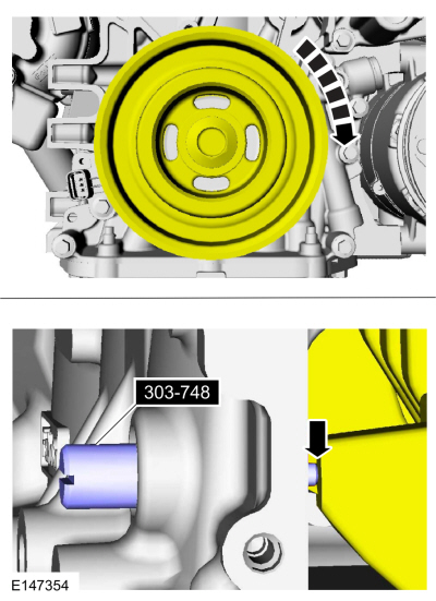
- Slowly rotate the crankshaft clockwise until the crankshaft counterweight contacts the TDC timing pin. The engine is now at TDC.
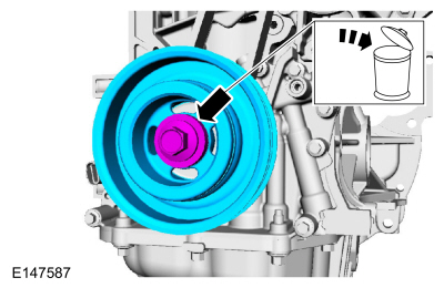
- Remove the bolt and the crankshaft pulley. Discard the bolt.
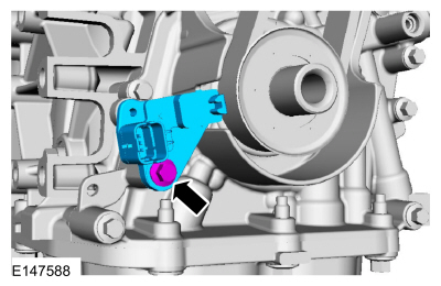
- Remove the retainer and the CKP sensor.
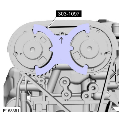
- Install the special service tool: 303-1097 Locking Tool, Variable Camshaft Timing Oil Control Valve.
- Rotate the timing belt tensioner clockwise.
- Install the retaining pin.
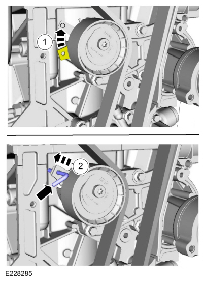
- Remove the timing belt.
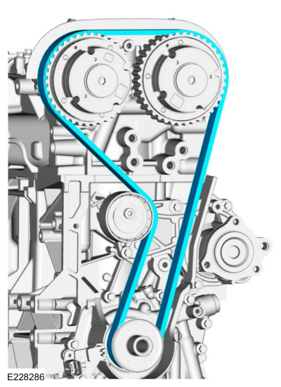
- Remove the crankshaft sprocket.
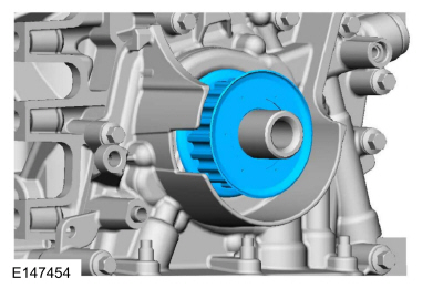
- Using special tools, remove and discard the front crankshaft seal.
Special Service Tools: 308-375 Input shaft seal remover, 100-001 (T50T-100-A) Slide hammer.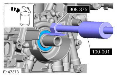
- Remove the retainer and the timing belt tensioner.
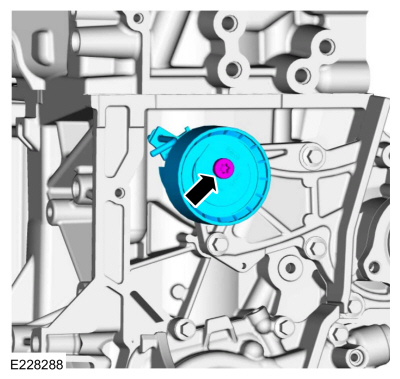
- Remove the bolts and the coolant pump. Discard the bolts.
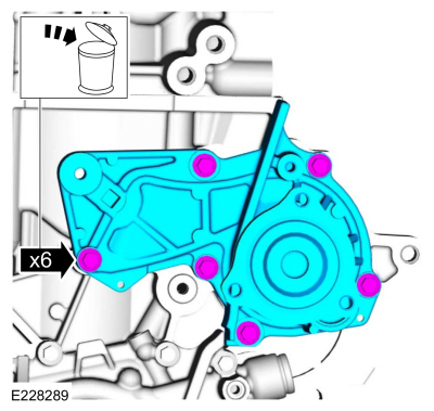
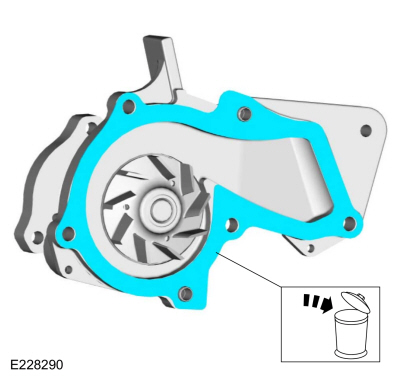
- Remove and discard the coolant pump gasket.
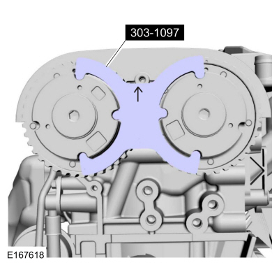
- Remove the special service tool: 303-1097 Locking Tool, Variable Camshaft Timing Oil Control Valve.
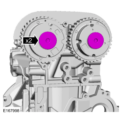
- Remove the VCT covers.
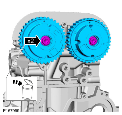
- Remove the bolts and the VCT units. Discard the bolts.
- Using the special tool, remove and discard the camshaft seals.
Use special service tool: 303-409 (T92C-6700-CH) Remover, Crankshaft Seal.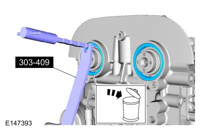
NOTICE: Use a heat gun to soften the flange sealant to assist in removing the camshaft cap. Failure to follow these instructions may result in damage to the camshaft cap.
NOTICE: Do not pry on the camshafts during removal as this may damage the camshafts.
- Remove the bolts and the camshaft caps.
- Heat and remove the camshaft cap.
Use common service equipment: heat gun.
- Remove the camshafts.
- Discard the camshaft bearing cap bolts.
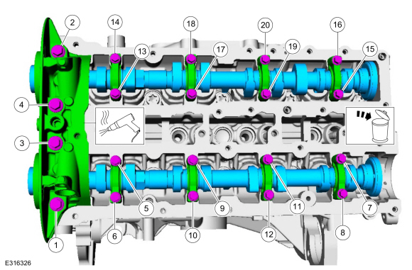
- Remove the crankcase ventilation drain tube.
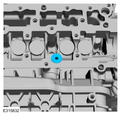
- Inspect the crankcase ventilation drain tube and replace it if damaged.
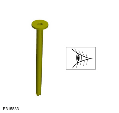
- Remove and discard the O-ring.
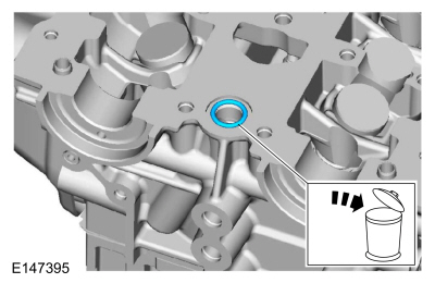
- Remove the valve lifters.
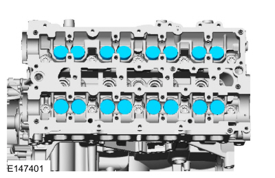
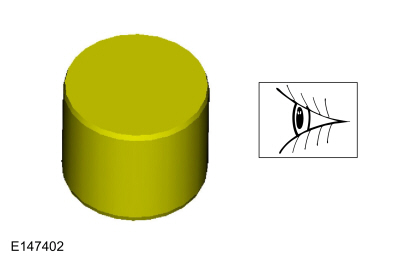
- Inspect and install new components as necessary.
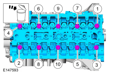
- Remove the bolts in the sequence shown and remove the cylinder head. Discard the bolts.
- Remove and discard the cylinder head gasket.
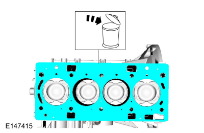
- Remove and discard the dowels.
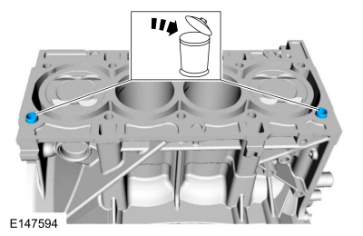
- Check the cylinder block and cylinder head for distortion.
Refer to: Cylinder Head Distortion (303-00 Engine System - General Information, General Procedures).
Refer to: Cylinder Block Distortion (303-00 Engine System - General Information, General Procedures). - Remove the special service tool: 303-748 Crankshaft Locking Tool.
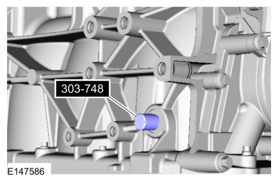
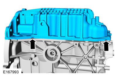
- Remove the oil pan bolts.
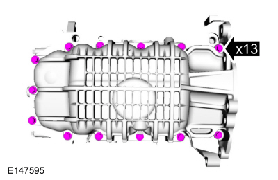
- Using suitable supports, remove the oil pan.
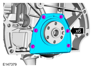
- Remove the bolts and the rear crankshaft seal.
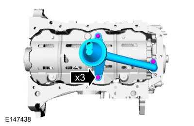
- Remove the bolts, the oil pump screen and the pickup tube.
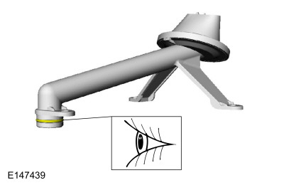
- Inspect the oil pump screen and the suction tube O-ring.
- Remove the bolts and the oil pan baffle.
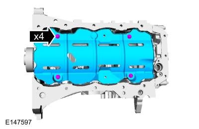
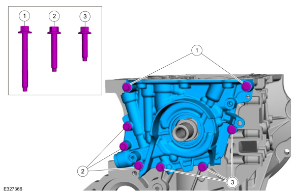
- Remove the two M6 x 55 mm bolts.
- Remove the three M6 x 35 mm bolts.
- Unscrew the three M6 x 25 mm bolts and remove the oil pump.
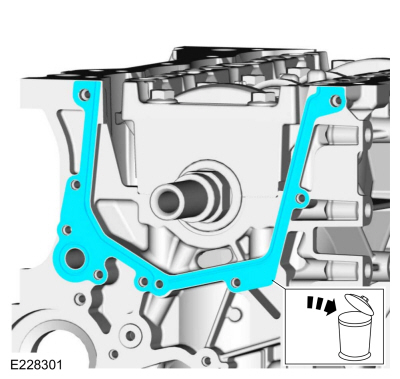
- Remove and discard the oil pump gasket.
- Clean the oil pump bolt holes with Motorcraft® Metal Brake Parts Cleaner to remove all oil residue.
Material: Motorcraft® Metal Brake Parts Cleaner / PM-4-A, PM-4-B
- Use compressed air to remove brake cleaner or oil from the oil pump bolt holes.
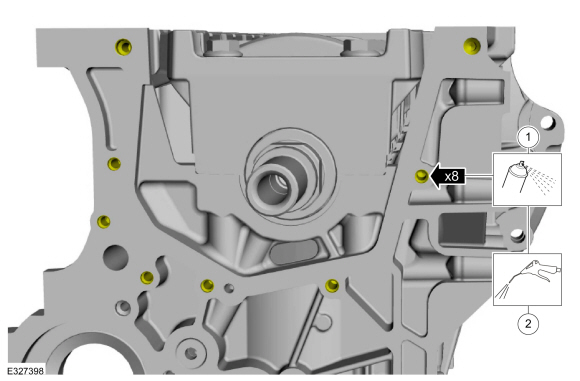
- Clean the oil pump bolt holes with Motorcraft® Metal Brake Parts Cleaner to remove all oil residue.
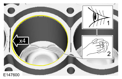
- Before removing the pistons, inspect the upper part of the cylinder bores.
- If necessary, remove the ridge or carbon deposits from each cylinder using an abrasive pad.
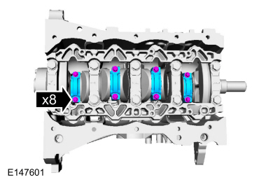
- Remove the bolts and the connecting rod caps.
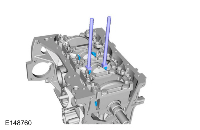
- Repeat with the connecting rod installation tool until all piston/connecting rod assemblies are removed from the cylinder block.
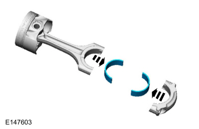
- Remove the connecting rod bearings.
- Inspect the pistons.
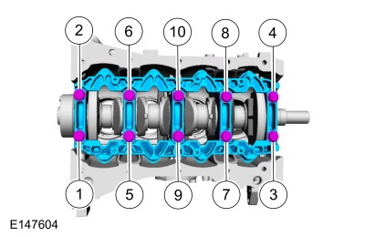
Refer to: Piston Inspection (303-00 Engine System - General Information, General Procedures). - Remove the bolts in the sequence shown and the main bearing beam.
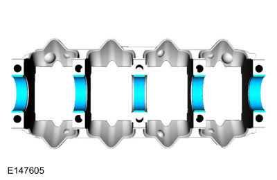
- Remove the crankshaft main bearings.
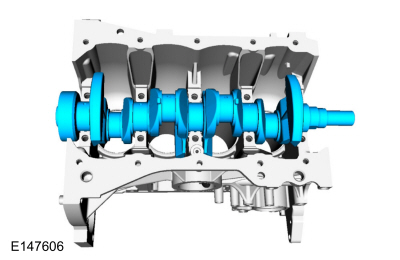
- Remove the crankshaft.
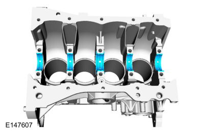
- Remove the crankshaft main bearings.
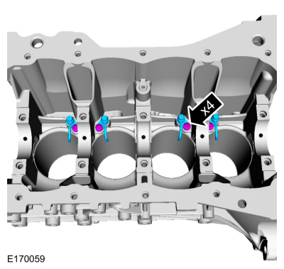
- Remove the bolts and the engine piston oil cooler valves.
Test yourself
A quick Ford Fusion quiz: every answer comes with an explanation and a link to the manual page.