AUTOMATIC TRANSMISSION SYSTEM
SHIFT LOCK SWITCH
In this manual: AUTOMATIC TRANSMISSION SYSTEM
29steps
~179min
5/5difficulty
1special tools
Done 0 of 29
Description and Operation
Description
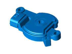
- The inhibitor switch is installed on the upper part of the transmission and is connected to the shift lever.
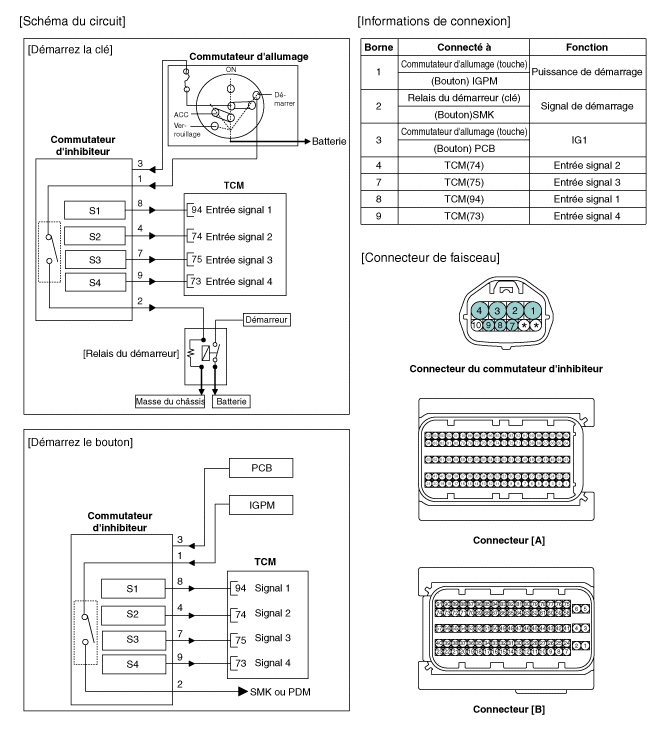
- The inhibitor switch has four contact points and outputs signals (S1, S2, S3, S4).
- The inhibitor switch signals sent to the TCM are based on the shift lever positions (P, R, N, D) and are used to control clutch engagement.
Specifications
Specifications
▷ Type: 4-terminal output signal combination| Supply voltage (V) | 12 |
| Output type | Output signal combination |
Signal Code Table
| P | P-R | R | P, R, N | NO | N-D | D | |
| S1 | 12V | 12V | 0 | 0 | 0 | 0 | 0 |
| S2 | 0 | 12V | 12V | 12V | 0 | 0 | 0 |
| S3 | 0 | 0 | 0 | 12V | 12V | 12V | 0 |
| S4 | 0 | 0 | 0 | 0 | 0 | 12V | 12V |
Circuit Diagrams
Wiring Diagram
Troubleshooting
Diagnostic Trouble Code Troubleshooting
Diagnosis by Symptom
| Main Symptom | Possible Cause | Components to Inspect and Remedy |
| Shift lever does not operate | Incorrect shift cable tension | Adjust the shift cable tension (Refer to Automatic Transmission System - Inhibitor Switch) |
| Incorrect shift cable connection/installation | Check the manual control valve assembly and reassemble if necessary. | |
| Incorrect shift cable bracket installation | Check the shift lever installation cable and repair if necessary. | |
| Shock when shifting to and from D/R Engine start when shifting to D/R and back |
Incorrect adjustment of the inhibitor switch "N" position | Use the adjusting tool for "N" and adjust "N". |
| (See Automatic Transmission System - Inhibitor Switch) | ||
| Low oil pressure in the valve body. | Replace the valve body, or inspect/replace the transmission. | |
| Engine starting malfunction Current speed not displayed on the instrument cluster Warning lamp illuminates Engine stalls when stopped Slow walking not possible Automatic parking trigger disabled |
Malfunction of CAN terminating resistor/CAN circuit | Check the battery management system module/PCU. |
| Check the PCU wiring connector connection. | ||
| Power supply (IGN.1) malfunction in the inhibitor switch circuit | Check the engine compartment junction box power terminal for looseness and the connection to the fuse (TCU2). Repair the terminal or replace the junction box if necessary. | |
| Inhibitor switch circuit fuse malfunction | Check the fuse and the junction box terminal, then repair. | |
| Faulty inhibitor switch wiring connector | Check the wiring connector for foreign material and check the terminal for looseness. | |
| Check the seal on the unused terminal and make sure the terminal is not corroded. | ||
| Back-up lamp circuit malfunction | Check the back-up lamp ground and reconnect it if necessary. | |
| Faulty ground of the inhibitor switch wiring | Check the wiring ground and reassemble if necessary. | |
| Inhibitor switch circuit malfunction (unused code) | Check according to the inspection procedure, then replace the switch. Replace the inhibitor if necessary. | |
| Inhibitor switch malfunction (mid-range malfunction) | Check according to the inspection procedure, then replace the switch. Replace the inhibitor if necessary. |
Repair Procedures
Inspection
Inhibitor switch inspection circuit
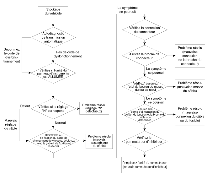
- Check the DTC.
- Check whether the N position setting is correct.
- Adjust the N position (see Automatic Transmission System - "Inhibitor Switch").
- Check the shift cable separation.
- Adjust the distance between the shift cables (see Automatic Transmission System - "Shift Cable").
- Check whether the connector is inserted.
- Check whether the connector is loose, poorly connected, or whether there is corrosion, contamination, deformation, or damage.
- Turn the ignition switch to ON and the engine to OFF, then measure the voltage and power supply in the inhibitor switch circuit between ground.
Specification: approximately 12 V
- Secure the pin wiring when the connector pin wiring is faulty. (See ETM - "Wiring Repair").
- Check the ground in the back-up lamp circuit.
- Check the back-up lamp ground location (see ETM - "Circuit Location Map").
- Connect the back-up lamp if the ground is faulty.
- Check the wiring connection at the power terminal of the junction box, the connection, and the fuse indicator.
- Check whether the fuse holder is separated and whether the fuse holder holds the fuse tightly.
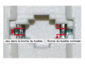
- Attach a test fuse to check whether the branch circuit is correct.
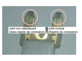
- Check whether the fuse rating is suitable for each circuit.
- Check whether the fuse is damaged.
- Check the inside of the inhibitor switch connector for foreign material, and check whether the terminal is bent.
- Reinstall the terminal that was removed, and check using the method described above.
- If the problem is not resolved, refer to the wiring diagram. Repair or replace the terminal.
- Check whether the fuse holder is separated and whether the fuse holder holds the fuse tightly.
- Check the shift lock switch signal.
- Turn the ignition switch to ON and the engine to OFF.
- Measure the voltage between each terminal and chassis ground when the shift lever is in the "P, R, N, D" position.
Specified value: See the specification table. "Signal code"
DEPOSIT
- Before adjusting the lever, make sure the vehicle does not roll. Shift to the "N" position.
- Disconnect the negative (-) battery cable.
- Remove the air duct and air cleaner assembly. (Refer to Engine Mechanical System - "Air Cleaner")
- Disconnect the battery and battery tray. (Refer to Engine Electrical System - "Battery".)
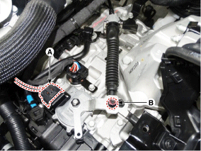
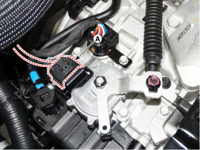
- Disconnect the shift lock switch connector (A).
- Remove the shift cable fixing nut (B).
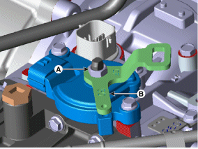
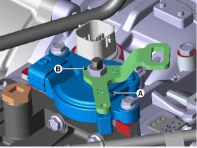
- Remove the manual control lever (B) and washer, then remove the nut (A).
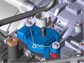
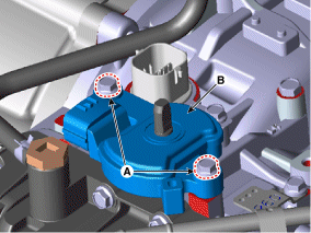
- Remove the inhibitor switch (A) after removing the 2 bolts (B).
REMEDY
- Make sure the shift lever is in the "N" position.
- Tighten the bolts (A) carefully after installing the inhibitor switch (B).
- Tighten the nut (A) carefully after installing the manual control lever (B).
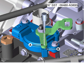
- Align the hole (A) in the manual control lever with the "N" position hole (B) of the inhibitor switch, then insert the SST guide pin of the inhibitor switch (SST No.: 09480-A3800).
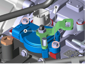
- Tighten the nut (A) and bolts (B) to the specified torque. Torque: A: 17.7 ~ 24 N·m B: 9.8 ~ 11.8 N·m
- Lightly tighten the nut (B) after connecting the shift cable (C) to the manual control lever (D).
- Lightly press the shift cable (C) in the direction shown by the letter "F" to remove slack in the shift cable.
- Tighten the nut (B) to the specified torque.
Tightening torque: 9.8 ~ 14.7 N·m
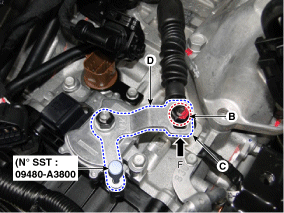
- Remove the inhibitor switch guide pin (SST No.: 09480-A3800) from the hole.
- Connect the inhibitor switch (A).
- Install the battery and battery tray. (Refer to Engine Electrical System - "Battery".)
- Install the air cleaner and air duct. (See Engine Mechanical System - "Air Filter").
- Connect the negative (-) battery cable.
- Make sure operation is safe in each inhibitor switch range corresponding to each shift lever position.
Test yourself
A quick Hyundai Tucson quiz: every answer comes with an explanation and a link to the manual page.
Was this page helpful?