AUTOMATIC TRANSMISSION SYSTEM
Transmission Control Module (TCM)
In this manual: AUTOMATIC TRANSMISSION SYSTEM
14steps
~84min
3/5difficulty
Done 0 of 14
Description and Operation
Description
- Monitors the vehicle operating conditions to determine the optimal shift speed setting.
- Performs gear shifting when the current gear setting differs from the determined optimal shift speed setting.
- Determines whether to engage the damper clutch (D/C) and engages the clutch accordingly.
- Calculates the optimal line pressure level by constantly monitoring the torque level and adjusting the pressure accordingly.
- Automatic Transaxle Troubleshooting and Failure Diagnosis.
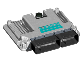
Circuit Diagrams
1. TCM Connector and Terminal Function

2. TCM Terminal Function
CONNECTOR [A]| Pin | Description | Pin | Description |
| 22 | Overdrive Clutch Control Solenoid Valve (OD/C_VFS) | 73 | Inhibitor Switch Signal (S4) |
| 23 | Pressure Control Solenoid (VFS-LINE) | 74 | Inhibitor Switch Signal (S2) |
| 26 | On/Off Solenoid Valve (SS-B) | 75 | Inhibitor Switch Signal (S3) |
| 37 | High Sport Mode Switch | 87 | Solenoid Power 1 |
| 38 | Sport Mode Select Switch | 88 | Solenoid Power 2 |
| 39 | Transmission Fluid Temperature Sensor (+) | 89 | On/Off Solenoid Valve A (SS-A) |
| 43 | Low Speed Brake Control Solenoid Valve (LR/B_VFS) |
94 | Inhibitor Switch Signal (S1) |
| 44 | 35R Clutch Control Solenoid Valve (35R/C_VFS) | 95 | Speed Sensor Output Power |
| 45 | Torque Converter Control Solenoid (T/CON_VFS) | 96 | Input Speed Sensor Power |
| 46 | 26 Brake Control Solenoid Valve (26/B_VFS) | 99 | Input Speed Sensor Signal |
| 58 | Low Sport Mode Switch | 100 | Output Speed Sensor Signal |
| 59 | Transmission Fluid Temperature Sensor (+) |
Connector "B"
| Pin | Description | Pin | Description |
| 1 | GROUND (POWER) | 5 | VB (Battery Voltage) |
| 2 | GROUND (POWER) | 60 | CAN High |
| 3 | VB (Battery Voltage) | 68 | IGN.1 (Ignition Switch) |
| 4 | GROUND (POWER) | 77 | CAN Low |
TCM Terminal Signal Input/Output
CONNECTOR [A]| Pin | Description | Condition | INPUT/OUTPUT VALUE | |
| Good | Level | |||
| 22 | Overdrive Clutch Control Solenoid Valve (OD/C_VFS) |
- | Output | Battery Voltage Level/0 V |
| 9 V < Battery Voltage Level < 16 V | ||||
| 23 | Line Pressure Control Solenoid Valve (LINE_VFS) |
- | Output | Battery Voltage Level/0 V |
| 9 V < Battery Voltage Level < 16 V | ||||
| 26 | On/Off Solenoid Valve (SS-B) | High | Output | Battery Voltage Level/0 V |
| Down | 9 V < Battery Voltage Level < 16 V | |||
| 37 | High Sport Mode Switch | HIGH ON | Input | Battery Voltage Level/0 V |
| Other | 9 V < Battery Voltage Level < 16 V | |||
| 38 | Sport Mode Select Switch | sport mode | Input | Battery Voltage Level/0 V |
| Other | 9 V < Battery Voltage Level < 16 V | |||
| 39 | Transmission Fluid Temperature Sensor (+) | WE | Input | 0 V/3.3 V |
| OFF | ||||
| 43 | Low Speed Brake Control Solenoid Valve (LR/B_VFS) |
- | Output | Battery Voltage Level/0 V |
| 9 V < Battery Voltage Level < 16 V | ||||
| Power Supply: V_SOL2 | ||||
| 44 | 35R Clutch Control Solenoid Valve (35R/C_VFS) |
- | Output | Battery Voltage Level/0 V |
| 9 V < Battery Voltage Level < 16 V | ||||
| 45 | Torque Converter Control Solenoid Valve (T/C_VFS) |
- | Output | Battery Voltage Level/0 V |
| 9 V < Battery Voltage Level < 16 V | ||||
| 46 | 26 Brake Control Solenoid Valve (26/B_VFS) |
- | Output | Battery Voltage Level/0 V |
| 9 V < Battery Voltage Level < 16 V | ||||
| Power Supply: V_SOL2 | ||||
| 58 | Low Sport Mode Switch | LOW ON | Input | Battery Voltage Level/0 V |
| Other | 9 V < Battery Voltage Level < 16 V | |||
| 59 | Transmission Fluid Temperature Sensor (+) | - | Ground | 0 V |
| 73 | Inhibitor Switch Signal (S4) | High | Input | Battery Voltage Level/0 V |
| Down | 9 V < Battery Voltage Level < 16 V | |||
| 74 | Inhibitor Switch Signal (S2) | High | Input | Battery Voltage Level/0 V |
| Down | 9 V < Battery Voltage Level < 16 V | |||
| 75 | Inhibitor Switch Signal (S3) | High | Input | Battery Voltage Level/0 V |
| Down | 9 V < Battery Voltage Level < 16 V | |||
| 89 | On/Off Solenoid Valve A (SS-A) | High | Output | Battery Voltage Level/0 V |
| Down | 9 V < Battery Voltage Level < 16 V | |||
| 94 | Inhibitor Switch Signal (S1) | High | Input | Battery Voltage Level/0 V |
| Down | 9 V < Battery Voltage Level < 16 V | |||
| 95 | Speed Sensor Output Power | WE | Output | 0 V/7.5 V |
| OFF | ||||
| 96 | Input Speed Sensor Power | WE | Output | 0 V/7.5 V |
| OFF | ||||
| 99 | Input Speed Sensor Signal | High | Input | 0.7 V/1.4 V |
| Down | ||||
| 100 | Output Speed Sensor Signal | High | Input | 0.7 V/1.4 V |
| Down | ||||
Wiring Diagram


Repair Procedures
Inspection
Transmission Control Module (TCM) Problem Inspection Procedure- TCM GROUND CIRCUIT TEST: Measure the resistance between the TCM and chassis ground using the rear of the TCM wiring harness connector as a checkpoint on the TCM side. Repair any problem if possible.
Specification: Below 1 Ω
- TCM CONNECTOR INSPECTION: Disconnect the TCM connector and perform a visual inspection of the ground terminals on the TCM side and the harness side to make sure there are no bent pins or poor contact pressure. Repair any problem if possible.
- If no problem is found in steps 1 and 2, the TCM may be faulty. If so, make sure there are no DTCs before replacing the TCM with a new one, then recheck the vehicle. If any DTCs are present, check them before replacing the TCM.
- ORIGINAL TCM SUBSTITUTION TEST: Install the original TCM (known good) on a verified vehicle and check the vehicle. If the problem reappears, replace the original TCM with a new one. If the problem does not appear, the problem is intermittent (refer to "Intermittent Problem Procedure" in "Basic Inspection Procedure").
DEPOSIT
- Turn the ignition switch to the OFF position.
- Disconnect the negative (-) battery cable.
- Remove the air filter and air duct. (Refer to Engine Mechanical System - "Air Filter")
- Disconnect the TCM connector (A).

- Disconnect the TCM connector (B).
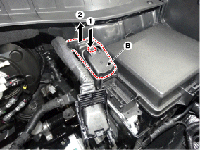
- Remove the retaining bracket (A) from the wiring harness.

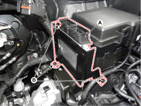
- Remove the TCM (A) by removing the mounting nuts and bolt (B).
TCM Mounting Nut: 9.8 - 11.8 N·m
REMEDY
- To install, perform the removal procedure in reverse order.
- Perform the ECM-related procedures after replacing the TCM. (Refer to Fuel System/Engine Control - "Engine Control Module")
- Perform TCM learning after replacing the transaxle to avoid sluggish shifting, acceleration, and harsh starts. (Refer to Automatic Transaxle Control System - "Repair Procedures")
Test yourself
A quick Hyundai Tucson quiz: every answer comes with an explanation and a link to the manual page.
Was this page helpful?